Gust Propagation
By default, Bladed Transient Gusts are spatially invariant and the wind speed or gust occurs simultaneously at all locations (including upwind and downwind).
This is not appropriate for use in conjunction with LIDAR as the wind speed will increase at both the rotor plane and the upstream focal point simultaneously.
There is an option to switch on a propagating gust with the transient model herein referred to as a propagating transient. This is important in LIDAR applications. The gust moves in the longitudinal direction at the speed of the start value of the gust using the following Project Info option.
MSTART EXTRA
GUSTPROPAGATION 1 * 0 switches off gust propagation (default), 1 switches on gust propagation
MEND
This model adjusts the lookup time of the transient wind speed model in order to model the advance of the gust.
Propagating Transient Behaviour
This section describes the behaviour of the propagating transient model. During a transient wind turbine simulation, the calculation code will "lookup" the wind speed at various locations on the turbine (blades, tower etc). It will interrogate the wind module based on the simulation time \(T\).
With gust propagation switched on the wind module modifies the simulation time at which the wind speed is looked up by \(\delta t = x/\bar{U}\). The variable \(x\) is the along wind position of the location measured from the global origin.
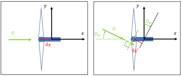
Consider a simple example of a hub with a overhang of \(4 \bunit{m}\) and \(\bar{U} = 8 \bunit{m/s}\). Then the wind speed "lookup" time is at \(\delta t = 0.5 \bunit{s}\) relative to when gust propagation is switched off. See Figure 1 for a schematic of this example.
Clearly if a LIDAR system was used the upwind lookup distance would be greater causing the lookup time to be much greater than in the above example. This enables feed-forward control to detect the gust travelling towards the wind turbine.
If the wind direction changes, then Bladed rotates the "wind field" around such that the updated alongwind position is \(x' = x\cos{\bar{D}_w})\), where \(\bar{D}_w\) is the mean wind direction defined as an input to the simulation. Note that the wind direction is looked up at the simulation time \(T\) and not the modified time due to the propagating transient. See Figure 1 for a schematic of this example.
Consider a second example where an extreme change in wind direction (ECD example) of amplitude \(15 \bunit{m/s}\) (half cycle) coincides with an increase in wind direction (half cycle) \(90 \bunit{deg}\). The transients occur at the same time T = 10 s and have the same duration.
The outputs of hub wind speed are shown in Figure 2 for the extreme change in wind direction simulation. The two outputs correspond to the situation where gust propagation is on and off. For the case where propagation in on the wind speed increases before the transient start time of T=10s because the speed is looked up at the hub which is upwind of the global origin.
In the case of example 2 above \(x^{'} \rightarrow 0\) as \(\bar{D}_w \rightarrow 90\ deg\) such that the gust on/off option is equivalent by the time the transient is complete. This can also be seen in Figure 2. In summary, the change in the shape of the hub wind speed profile between the two cases is because the wind direction changes.
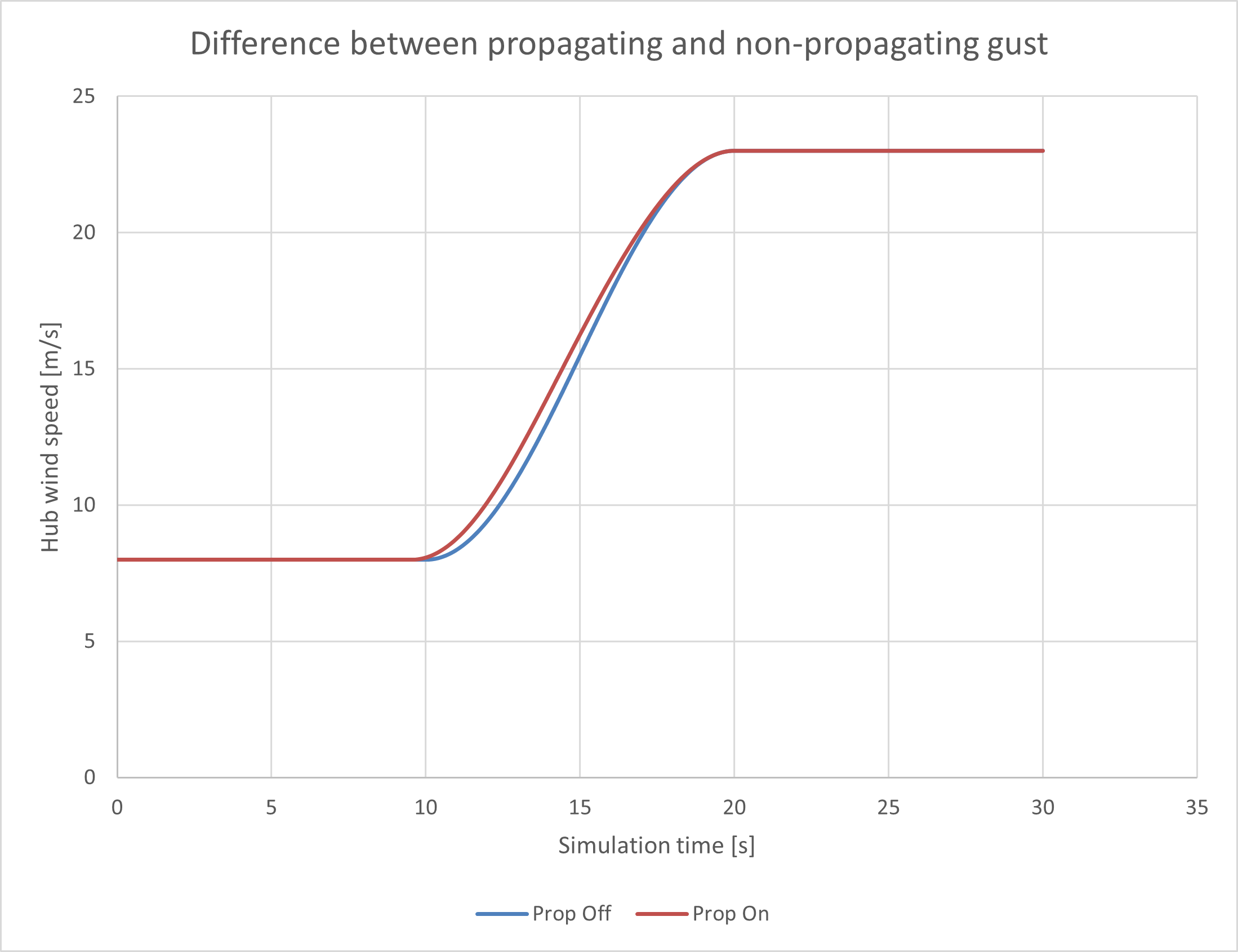
and wind speed increase from 8m/s to 23 m/s. The two curves relate to switching the gust propagation on/off.
Propagating Transient Limitation
The option to model a transient as a propagating gust is not accurate when a large direction is also included. The results presented in Figure 2 only focused on the hub wind speed which varies little between the non-propagating and propagating cases. However, the wind speed at the blade tips can be much larger as discussed below.
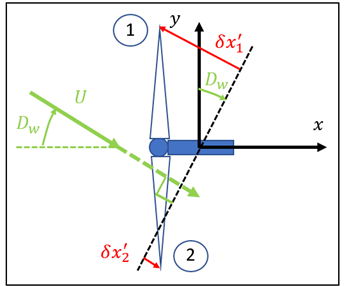
This section focuses on the ECD example that was described above. In addition, consider a wind turbine with two blades that are both horizontal during some instance in time. Figure 3 shows a larger wind direction change and the alongwind distance measured from the inertial origin to the blade tip for each blade. In this situation blade 1 has a positive lookup time whereas blade 2 will have a negative lookup time. This means that the wind speed transient will increase more quickly on blade 1 than it will on blade 2.
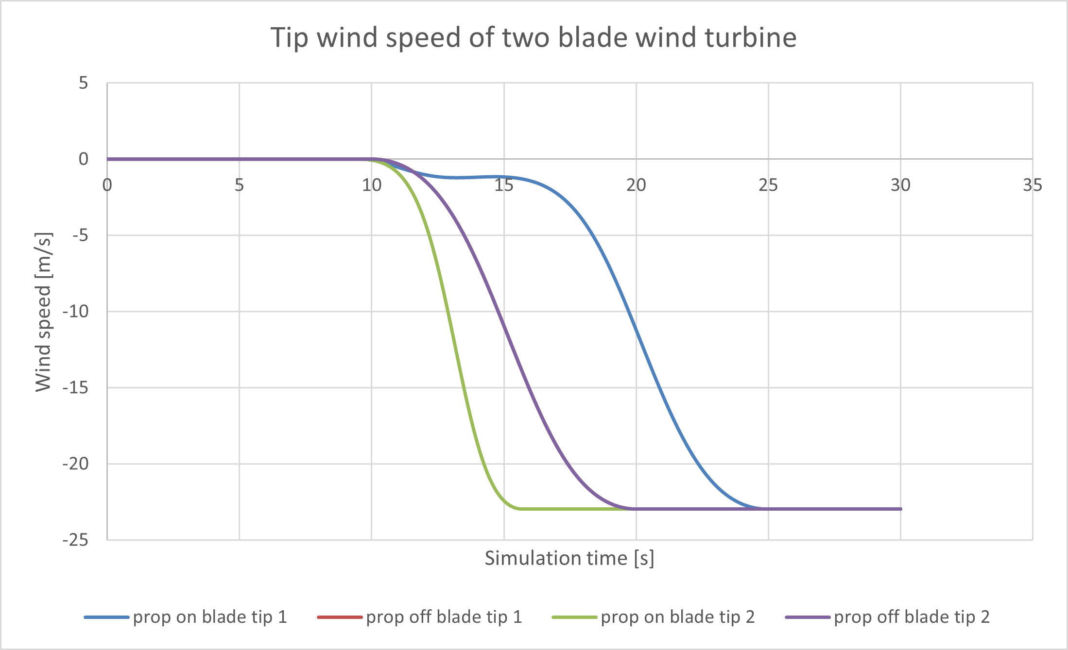
This issue can readily be observed the case of a wind turbine with two blades which are horizontal. Figure 4 shows the outputs of the local lateral wind speed at the blade tips. It is clear to see that in the case where gust propagation is on that the speed at blade tips 1 and 2 are significantly different in comparison to the scenario where gust propagation is off where the speed is identical at both blades.
This imbalance in the wind speed in the propagating gust case may lead to large changes in the stationary hub Myz load component relative to the scenario where gust propagation is off.
Writing a Wind File to Model a Propagating Transient
An alternative method of how to model the propagating wind field but to avoid the unphysical changes in wind speed across the rotor plane as outlined above is to write a Wind File and use this to model the transient instead.
It is recommended that a time series is created that matches the hub height wind speed, direction and upflow of the desired transient.
Normalise this time series and write the data to a Wind File using the description of the Wind File format that is available on the Bladed portal.
Use the appropriate starting wind speed and set the turbulence intensity to create the correct amplitude of transient.
General notes on results differences
There will remain some results differences between the scenario where a transient is modelled using a 3D Wind File and the standard transient model.
Any remaining discrepancies in the load outputs will most likely be attributed to the fact that speed changes will occur on blades at different times (when using the Wind File) which cause a load imbalance across the rotor.
Last updated 28-08-2024