The Variable Speed Stall Regulated Controller
Use this control model for a variable speed turbine (using example a Variable Speed Generator which uses the aerodynamic stall characteristics of the rotor to control the power above rated wind speed.
The Variable Speed Stall Regulated Controller
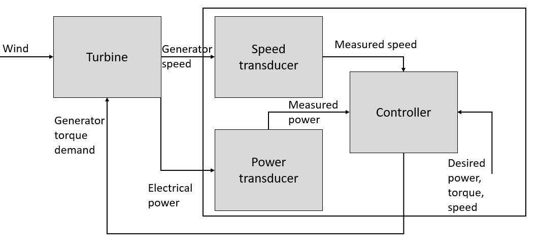
This controller model is appropriate to variable speed turbines which employ a frequency converter to decouple the generator speed from the fixed frequency of the grid, and which do not use pitch control to limit the power above rated wind speed. Instead, the generator reaction torque is controlled so as to slow the rotor down into stall in high wind speeds. The control loop is shown schematically in Figure 1.
Steady State Parameters
The steady-state operating curve can be described with reference to the torque-speed graph shown in Figure 2. In the partial load regime, between points B and C, it is possible to maximise energy capture by following a constant tip speed ratio load line which corresponds to operation at the maximum power coefficient. This load line is a quadratic curve on the torque-speed plane, shown by the curve BC in Figure 2. This curve is defined using the Optimal Mode Gain which when multiplied by the square of the generator speed returns generator torque. Alternatively, a lookup table of generator torque against generator speed could be defined.
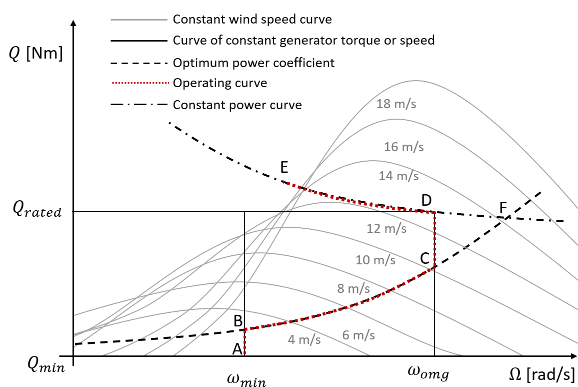
The curve BC is limited at point B by the Minimum Generator Speed and point C corresponding to the Optimal Mode Maximum Speed.
At low wind speeds the turbine is operated at the minimum speed along the line AB shown in the
figure. Similarly in high wind speeds, once the maximum operating
speed then once again it is necessary to depart from the
optimum load line by operating at nominally constant rotor speed along the
line CD.
Once Demanded Shaft Power is reached at point D, it is necessary to slow the
rotor speed down into stall, along the constant power curve DE. If high
rotational speeds are allowed, governed by the Maximum Generator Speed, it is possible for the line CD
to collapse so that the constant power curve and the constant tip speed
ratio line meet at a point F.
Last updated 10-09-2024