Beam Direction
This section explains how a user can define the LIDAR beam direction, relative to a mounting component, in the user interface. The LIDAR beam is specified using a LIDAR axis which describes the orientation of the LIDAR system relative to the mounting node. The beam direction is then defined relative to the LIDAR axis and this can vary depending on the scanning pattern; or remains fixed on the LIDAR axis if the fixed scan pattern is specified.
The user can add multiple LIDAR beams in the user interface. These can be mounted on the nacelle, hub or at a blade station. The body-fixed coordinate system \((x_b, y_b, z_b)\) used depends on the component. The rotating hub coordinate system is used if mounted on the Spinner, the yaw bearing coordinate system is used if mounted on the nacelle and the root axes coordinate system is used if mounted on a blade station. A position offset \((X,Y,Z)\) translates from the body-fixed to a local frame \((x_l, y_l, z_l)\) with origin \(O_l\). The nominal (undeflected) LIDAR axis is specified relative to the local frame by a sequence of two rotations. The first rotation is about the \(y_l\) axis by the the inclination angle \(\theta\), the second rotation is about the \(x_l\) axis by the azimuth angle \(\psi\), as shown in Figure 1.

The direction of each beam will change at run-time according to the motion of its mounting component, the LIDAR axis and the scanning pattern defined by the user or external controller. Static and dynamic deflections of the mounting component will also affect the LIDAR beam’s orientation and position. For instance, if mounted on the spinner, the LIDAR system will be inclined if the hub has a tilt angle. Likewise, if the nacelle is yawed, the LIDAR system will also be yawed accordingly and if mounted on the blade, the LIDAR system will rotate as the rotor azimuth angle varies.
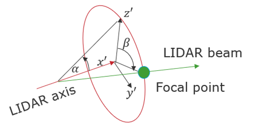
A laser beam can be steered to scan an area in front of the turbine referred to as a scan pattern. The scan pattern describes the variation in the beam direction relative to the LIDAR axis with respect to time. The beam direction is defined by a spherical coordinate system defined using two angles \(\alpha\) and \(\beta\), as denoted in Figure 2. The angles \(\alpha\) and \(\beta\) represent the inclination to and the azimuthal rotation about the LIDAR axis.
LIDAR scan patterns
The user can apply one of the pre-defined scanning techniques, fixed position, circular scanning or rosette scanning. If the fixed scan pattern is selected, then the beam direction is coincident with the LIDAR axis. Otherwise the beam direction is updated as per the governing scan pattern equation.
The number of samples per complete scan \(N_{s}\), should be specified by the user along with the sampling rate \(T_{s}\). The period of each scan is then given by \(T = T_{s} \cdot N_{s}\).
If a scanning pattern is selected when there is more than one beam defined, the same scanning pattern is assumed for all beams. This limitation can be avoided, if the scan pattern is defined by the external controller.
Last updated 18-10-2024