Nacelle Mass and Inertia
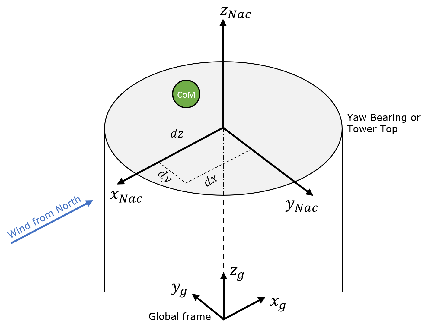
Check the Assign Mass (excluding rotor and hub) checkbox to define the nacelle mass characteristics required for dynamic calculations. This includes the nacelle structure and all the machinery within it. It does not include the rotor blades and hub. If the Direct Drive option is selected, the mass of the generator is also excluded. The user should input the Mass of the nacelle and Position of the centre of mass (\(x_{Nac}\), \(y_{Nac}\), \(z_{Nac}\)) defined relative to the tower top as shown in Figure 1. The user must also specify the nacelle yaw \(\bscalar{I}_{\text{Nac,Yaw}}\), nodding \(\bscalar{I}_{\text{Nac,Nod}}\) and roll inertias \(\bscalar{I}_{\text{Nac,Roll}}\).
Note
The orientation of the nacelle centre of mass (CoM) coordinate system remains the same for up- and downwind configurations. Thus the user needs to redefine the location of the centre of mass when switching between up- and downwind configurations. The CoM coordinate system is positioned at the yaw bearing node (YB) if defined, or tower top (TT) if no yaw bearing is defined. The defined mass rotates with the yaw motion of the nacelle.
Note
The Turbine Information window shows the total masses and inertias
of all turbine components whose mass characteristics are defined. Use
the pull-down menu on the main toolbar to open this window.
Nacelle Mass for Direct Drive Case
In the case of a direct drive transmission type the nacelle mass and generator mass are combined into one lumped mass for the nacelle. To compute the new nacelle centre of mass we apply the following the equations.
and
where
\(\bscalar{l}\) is the lateral offset, which is the horizontal offset between the shaft and tower axes
\(\bscalar{h}\) is the total hub height
\(\bscalar{h}_t\) is the tower height
\(\bscalar{\theta}\) is the tilt angle
\(\bscalar{z}_{\text{hub}}\) is the centre of mass position of the hub
\(\bscalar{z}_{\text{DD}}\) is the centre of mass position of the direct drive generator
\(\bscalar{o}\) is the overhang, which is the horizontal distance between the rotor centre and the tower centreline
\(\bscalar{m}_{\text{Nac}}\) is the nacelle mass
\(\bscalar{x}_{\text{Nac}}\) is the nacelle centre of mass x position
\(\bscalar{y}_{\text{Nac}}\) is the nacelle centre of mass y position
\(\bscalar{z}_{\text{Nac}}\) is the nacelle centre of mass z position
\(\bscalar{m}_{\text{DD}}\) is the direct drive generator mass
\(\bscalar{x}_{\text{DD}}\) is the direct drive generator centre of mass x position
\(\bscalar{y}_{\text{DD}}\) is the direct drive generator centre of mass y position
\(\bscalar{z}_{\text{DD}}\) is the direct drive generator centre of mass z position
The new nacelle inertia properties are then defined as
where
\(\bscalar{I}_{\text{Nac,Yaw}}\) is the nacelle yaw inertia,
\(\bscalar{I}_{\text{Nac,Nod}}\) is the nacelle nodding inertia,
\(\bscalar{I}_{\text{Nac,Roll}}\) is the nacelle rolling inertia,
\(\bscalar{I}_{\text{DD}}\) is the direct drive generator inertia along the shaft, and
\(\bscalar{I}_{\text{DD,Perp}}\) is the direct drive generator inertia perpendicular to the shaft.
Note
The direct drive generator inertia is not corrected for tilt (last term in Equations \(\eqref{eq:INacYaw}\) and \(\eqref{eq:INacRoll}\)).
Last updated 28-08-2024