Hub Coordinate System
To configure hub outputs, click Other Outputs on the Calculation Outputs Specification screen.
The coordinate system for the hub load and deflection outputs from the calculations is based on the convention below.
Stationary Hub Loads
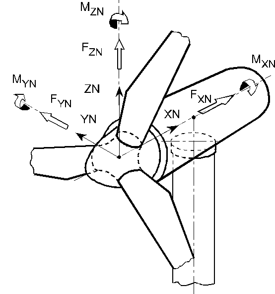
Hub loads in fixed frame of reference:
XN, Along shaft axis, and pointing towards the tower for an upwind turbine, or away from the tower for a downwind turbine (the picture shows an upwind turbine).
ZN, Perpendicular to XN, such that ZN would be vertically upwards if the tilt angle were zero.
YN, Horizontal, to give a right-handed coordinate system independent of direction of rotation and rotor location upwind or downwind of the tower.
Rotating Hub Loads
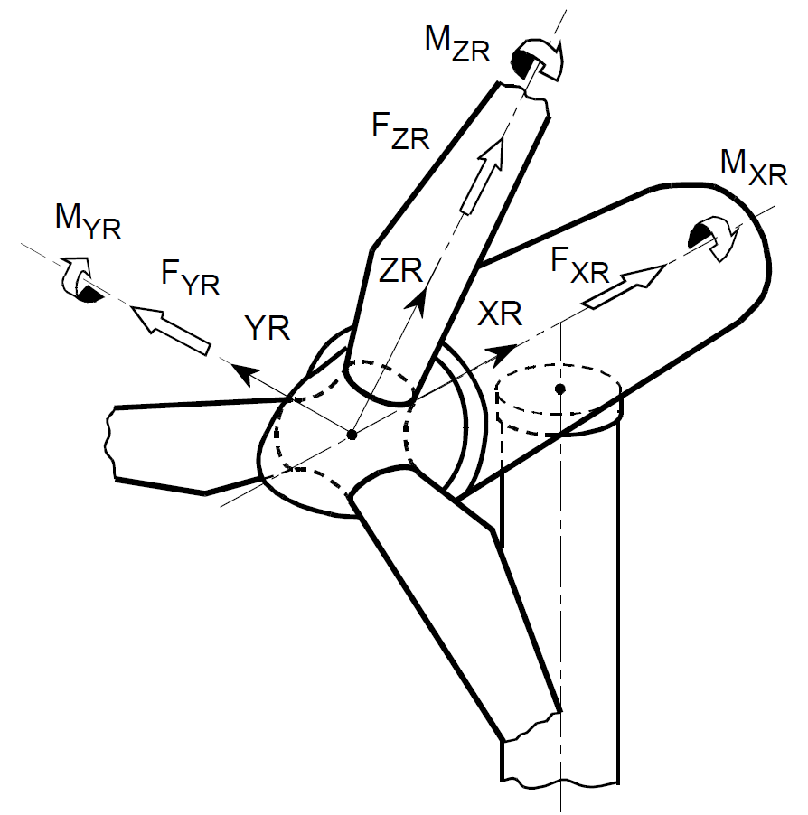
Hub loads in rotating frame of reference:
XN, Along shaft axis, and pointing towards the tower for an upwind turbine, or away from the tower for a downwind turbine (the picture shows an upwind turbine).
ZN, Perpendicular to XN, such that ZN would be aligned with the blade pitch axis if the cone angle were zero.
YN, Perpendicular to XN and ZN, to give a right-handed coordinate system independent of direction of rotation and rotor location upwind or downwind of the tower.
Origin at hub centre (intersection of blade and shaft axes).
Last updated 28-08-2024