Teeter Hub
For one and two bladed rotors, click the check box to specify a teetered hub. For teetered hubs the user can select a delta-3 hinge. For Delta-3 enter a Delta-3 angle if pitch-teeter coupling is required. A positive delta-3 angle acts to stabilise teeter by increasing the angle of attack when the blade teeters into the wind.
Simple Teeter Restraint
A spring and damper model of a teeter restraint system is provided. If a teetered rotor has been specified, click the Teeter restraint button on the Hub screen, select Standard model, and enter the
following parameters:
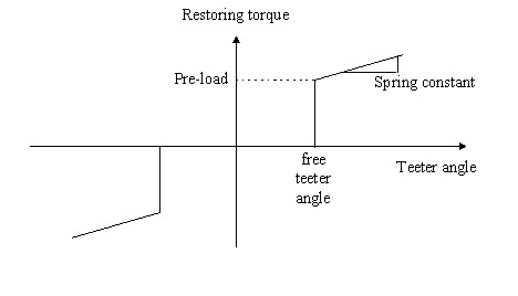
Free teeter angle- The teeter restraint only starts to act when this teeter angle is exceeded.Spring preload- The torque required to start moving the teeter restraint.Spring stiffness- The rotational stiffness of the teeter restraint.Teeter damping- The rotational damping of the teeter restraint.
If the teeter hinge has a delta-3 angle, the teeter restraint is on the flapwise motion resolved through the delta-3.
The Model
The teeter restraint model available in Bladed for teetered rotors is described here. The model allows a linear variation of restoring torque with teeter angle, but also allows a free teeter range and an initial pre-load. Figure 1 defines the relevant parameters. Linear damping is also allowed, giving an additional torque contribution proportional to teeter rate.
Additional Teeter Restraint Models
The Bladed user interface allows definition of simple linear stiffness and damping of the teeter hinge, as well as the ability to have a free teeter angle (below which teeter stiffness and damping = 0) and a spring preload torque. This section describes some additional models for the restraint torque, covering non-linear stiffness and damping terms and teeter hinge friction.
Non-linear Teeter Stiffness
A lookup table for teeter restraint stiffness can be defined as below.
MSTART EXTRA
NKTEET2 4                           * number of points in lookup table
KTEET2ANGLE -0.1 -0.01 0.01 0.1     * teeter angle (radians)
KTEET2TORQUE -10000 0 0 10000       * teeter restraint torque (Nm)
MEND
Non-linear Teeter Damping
There are two non-linear teeter damping options available through Project Info, with either a linear or quadratic dependence on teeter velocity.
The damping torque follows one of the following two formulae:
Linear Damper:
Quadratic Damper:
where \(\gamma\) is the teeter angle in delta-3 coordinates. \(K_{a}\) and \(b\) are parameters that must be specified.
For the quadratic damper model, it is also possible to specify a teeter rate below which a linear damping model is used. This can help with stability of the quadratic damper at low teeter rates. When the teeter rate is below (the constant value) \({\dot{\gamma}}_\text{D2LIN}\), a different equation is used to work out the damping.
Quadratic damper linear region:
The damper is active when the teeter angle is greater than \(\gamma_{0}\), and only when the motion is away from zero degrees. Additionally the damping is capped at a maximum damping torque and when the teeter angle is greater than \(\gamma_{1}\) , the damping torque always takes the maximum value.
Example parameters to be entered in Project Info:
MSTART EXTRA
DELTA3DAMP 1        * Enables non-linear damper. Value = 1.
TEETERK 120000      * Ka
TEETERGAM0 0.0872   * γ0 (rad)
TEETERGAM1 0.1919   * γ1 (rad)
EXPONENT 100        * b (if b = 0 is wanted, use b = 0.0000001)
TEETERMMAX 400000   * Maximum damping torque (Nm)
LINEARDAMP 0        * 0 for “Linear damper” and 1 for “Quadratic damper”
D2LINGAMMA 0.1      * Teeter rate (rad/s) below which “quadratic damper linear region” used
MEND
Teeter Friction and Stiction
A stick-slip friction model can be applied to the teeter hinge. Constant friction and stiction torques can be defined. The friction torque is the “kinetic friction” that describes the friction torque experienced while the hinge is in motion. The stiction torque is additional friction torque only present when the hinge is stationary. In order for the teeter hinge to move (assuming no other restraints), the torque acting on the hinge must be greater than the sum of the constant friction and stiction terms.
Enter the following code into Project Info.
MSTART EXTRA
TEETERFRICTION 1000     * Teeter spring friction (Nm)
TEETERSTICTION 600      * Teeter spring stiction (Nm)
MEND
Combining Teeter Restraint Functions
If it is desired to include more than one of the above teeter functions in a single simulation, the lines must be entered in the order shown below. Any complete set of lines (for example all three lines relating to non-linear stiffness) can be omitted if that functionality is not required.
MSTART EXTRA
DELTA3DAMP 1
TEETERK 120000
TEETERGAM0 0.001745329
TEETERGAM1 0.013962634
EXPONENT 100
TEETERMMAX 4000
LINEARDAMP 1
D2LINGAMMA 0
NKTEET2 4
KTEET2ANGLE -0.1 -0.01 0.01 0.1
KTEET2TORQUE -10000 0 0 10000
TEETERFRICTION 1000
TEETERSTICTION 1000
MEND
Teeter Offset and Hub Centres of Mass
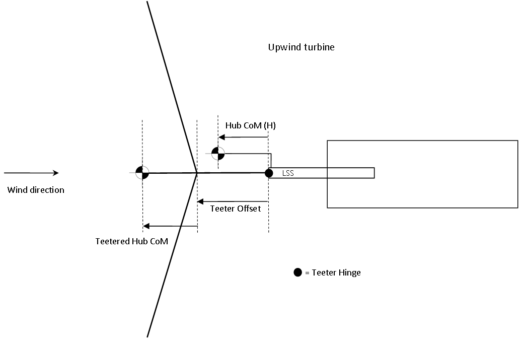
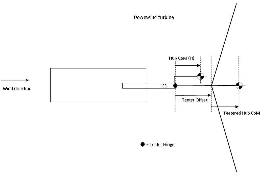
This section describes the functionality and conventions regarding mass and geometry definitions for the hub of a teetered turbine. The sign conventions for defining the hub centres of mass and teeter offset are shown in Figure 2 and Figure 3.
Hub Centres of -mass
For teetered turbines, the overall mass and inertia of the hub is considered in two separate parts. Firstly, the total mass of the ‘non-teetering parts’ (labelled as the ‘Hub CoM’ on figures 1 and 2) is defined relative to the end of the Low Speed Shaft (LSS). Secondly, the mass of the ‘teetered’ parts of the hub (labelled ‘Teetered Hub CoM’ on the figures) is defined relative to the rotor centre. The sum of the ‘Hub’ mass and the ‘Teetered Hub’ mass equals the total hub mass.
The hub mass and inertia defined in the User Interface refers to the parts of the hub that are ‘non-teetered’, in other words that are placed inboard of the teeter hinge, directly on the LSS. Teetered hub mass (i.e. outboard of the teeter hinge) should be defined with the following Project Info code.
MSTART EXTRA
THUBMAS 11460   *Teetered hub mass (kg)
THUBCTR 0.15    *Teetered hub centre of mass offset from rotor centre (m)
THUBINE 1000    *Teeter hub inertia about rotor rotational axis (kgm2)
THUBINE2 1000   *Teeter hub inertia about other orthogonal axes (kgm2)
MEND
Teeter Offset
In practice, teetered designs with coned rotors or blades with pre-bend will usually have a ‘teeter offset’ which is the axial distance from the rotor centre to the teeter hinge. This offset is designed to ensure that the rotor centre of mass is directly above the teeter hinge axis. If this were not the case, then at low rotor speeds the rotor would tend to fall away from the intended vertical position.
In Bladed, this offset is defined in Project Info. According to the conventions described in figures 1 & 2, the teeter offset in Bladed will be a negative number if the rotor is coned away from the support structure. This would be the case for both upwind and downwind designs.
MSTART EXTRA
TEETEROFFSET -0.3   *Teeter offset (m)
MEND
Hub Geometry Sign Conventions
The sign conventions for defining the teeter offset and hub centres of mass are shown in Figure 2 and Figure 3.
The non-teetered hub centre of mass and teeter offset are defined relative to the end of the LSS, whereas the teetered hub centre of mass is defined relative to the rotor centre. A change in teeter offset therefore changes the position of the teetered hub centre of mass. All of these parameters are defined as “positive away from the tower” for both upwind and downwind turbines. This sign convention has the advantage that the same geometrical parameters should be suitable for both an upwind and a downwind turbine.
Last updated 10-09-2024