Member End Offsets
The member end offset feature allows the user to define an offset at each end of each beam in a multi-member support structure. These offsets are modelled as rigid massless links. An offset is defined by a 3D vector that is specified in the members grid in the Tower screen, as shown in Figure 1. The origin of each vector is the node at the corresponding member end. By default, all offsets are set to zero.
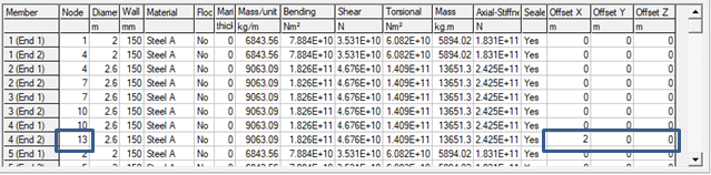
node and offset data defined at the member end.
Implementation
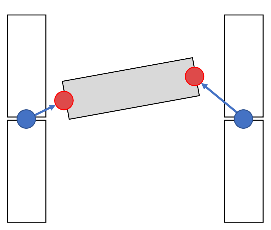
Wherever a non-zero offset vector is specified, a new flex-body node is created (called an offset node) and a rigid massless link is created (called an offset). The member being offset (the offset member) is connected to the offset node if one is created. The offset link is connected to the original node and the offset node. To find the location of the original node a user should note the node ID in the Node column of the member grid and find its coordinates in the nodes grid.
For example, using the grid in Figure 1, if Member 4, End 2 (Node 13) is offset by 2 metres in the X direction, the following happens during the analysis:
- A new offset node is created at the location \((x_{13} + 2 , y_{13} , z_{13})\).
- A rigid link is created between Node 13 and the offset node.
- Member 4 is moved so that its End 2 attaches to the offset node.
When tower internal loads are reported in Bladed, the loads are provided at the ends of the selected member. For an offset beam the ends are at the offset node locations.
Modelling assumptions
The stiffness, mass per unit length and inertia properties defined in the tower grid are unchanged when defining the flexibility properties of the offset member. Only the flexible part of the member attracts loading. The rigid massless link attracts no aerodynamic or hydrodynamic forces.
External forces applied to a flexible member, for example when using the "point loading" feature, must be applied at a distance \(L\) along that member, where \(L\) is no greater than the length of the member. On an offset member \(L\) must not be greater than the new length of the offset member.
Limitations
Functionality that is not supported or conditionally supported when using member end offsets is listed below:
| Features | Compatible with Member End Offset | Comments | Workaround |
|---|---|---|---|
| Display Structure | No | The implementation of member end offsets described in the above sections and in Figure 2 takes part virtually during the analysis. Therefore, the member end offsets are not shown in the Display Structure window. | Member end offsets can be visualised in Sesam Genie. |
| Nodal results | Partial | Nodal results, like deflections and water particle kinematics, are only outputted at the original mesh nodes. Results for the offset nodes are not available in the output files. | |
| Bar elements | No | Not supported |
Defining offset data
Member end offsets can be imported from a Sesam-generated Bladed project file. The user will need to use Sesam Wind Manager 5.3 to include the member end offset data in a jacket structure model exported to a Bladed project file.
While manual input of member offset data is supported in the multi-member tower definition window, it is advised that the offset values are not edited by users and are imported from Sesam Wind manager instead.
It is recommended that the tower internal load output option in Bladed is switched on to complete structural analysis of an offshore structure. This is because the tower internal loading results are read by Sesam and then post-processing is carried out using Sesam Wind Manager
Last updated 16-08-2024