Turbulent Wake State Model
When the axial induction factor \(\bscalar{a}\) becomes larger than approximately 0.4, the rotor enters what is known as the turbulent wake state and the classical BEM theory becomes invalid. As an example the momentum theory predicts that the flow in the far wake starts propagating up-stream when \(\bscalar{a \gt 0.5}\). Physically this flow reversal cannot occur. Glauert developed an empirical correction to the rotor thrust coefficient \(\bscalar{C_T}\) based on experimental measurements of helicopter rotors with large induced velocities. This correction that is described in Glauert, 1926b is shown in Figure 1 together with the thrust coefficient predicted by classical BEM theory and other correction models (see Bangga, 2022a).
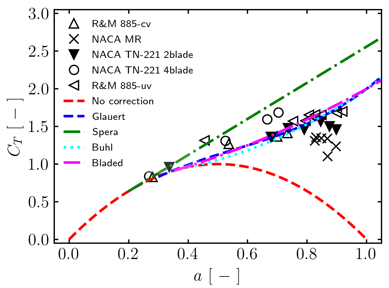
In Bladed, the turbulent wake state effect is corrected using a slight modified version of the Glauert correction model (Glauert, 1926b). The equations for thrust is changed into a simplified quadratic equation shown in Equation \(\ref{eq_glauert_bladed_turbwake_thrust}\). The equations for other models are provided in textbooks such as (Hansen, 2015; Bangga, 2022). The difference with the original Glauert model and other models is highlighted in Figure 1. The mass flow correction is applied as a correction factor \(\bscalar{f_g}\) to the axial induction factor \(\bscalar{a}\) or alternatively the axial induction component \(\bscalar{v_n}\) in the expression for the mass flow. For an ideal rotor the expression for the mass flow equation is given by
where \(V_0\) is the wind speed at the blade station in the [Glauert] form of the equation. If the user selects the axial momentum option then \(V_0 = V_x\) is used instead which is the wind speed projected into the drive train axial direction.
Note
The axial option is invalid for high yaw angles as the mass flow through the blade element will reduce to zero which is unphysical.
The Glauert correction can then be expressed in the form
with the following definitions for \(\bscalar{c_0}\), \(\bscalar{c_1}\) and \(\bscalar{c_2}\)
This implies that the thrust coefficient is expressed in the form
Last updated 13-09-2024