The Electrical Network
Provided either the detailed electrical model of the induction generator or the variable speed generator model is used, so that electrical currents and voltages are calculated, and reactive power as well as active power, then the characteristics of the network to which the turbine is connected may also be supplied. As well as allowing the voltage variations, and hence the flicker, at various points on the network to be calculated, the presence of the network may also, in the case of the directly connected induction generator, influence the dynamic response of the generator itself particularly on a weak network.
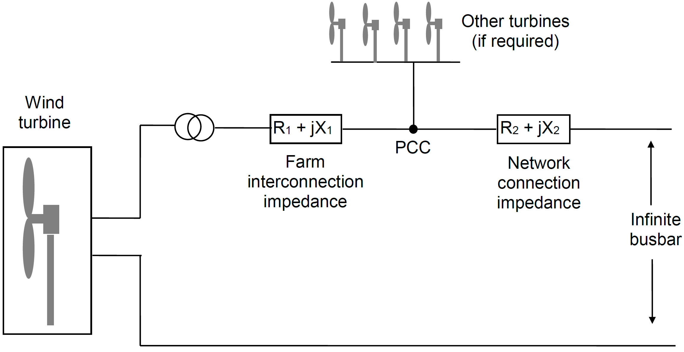
The network is modelled as a connection, with defined impedance, to the point of common coupling (PCC in Figure 1) and a further connection, also with defined impedance, to an infinite busbar. Further turbines may be connected at the point of common coupling. These additional turbines are each assumed to be identical to the turbine being modelled, including the impedance of the connection to the point of common coupling. However they are modelled as static rather dynamic, with current and phase angle constant during the simulation. The initial conditions are calculated with the assumption that all turbines are in an identical state, and the ‘other’ turbines then remain in the same state throughout. Thus the steady state voltage rise due to all the turbines at the point of common coupling will be taken into account in calculating the performance of the turbine whose performance is being simulated.
Last updated 30-08-2024