Output of Blade Loads
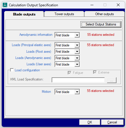
View available Blade outputs, as seen in Figure 1, by clicking the Calculation Outputs... button on the Calculations screen.
The outputs must be for either the First blade, All blades, or not at all (None).
The output settings defined here do not affect the Aerodynamic Information, Performance Coefficients and Steady Power Curve calculations, as they produce a pre-defined set of outputs.
A customised blade load output file can also be created and is described in the section on Load Configuration File.
Read more about the coordinate systems where the loads outputs are available in the following links:
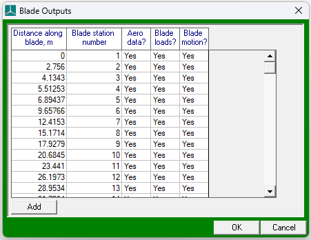
For each of the output categories in the Blade outputs, the information may be generated at any or all of the blade stations.
Click Select Output Stations to determine which information is required at which stations.
Click Add to define additional points where interpolated loads will be output.
It is important to note that the principal elastic axes and root axes stations coincide with the underlying finite beam element model nodes. The root axes coordinates have the same origin rotated to align with the blade root. The aerodynamic and user axes potentially have origins that do not coincide with the underlying finite element beam model nodes. These load outputs are found by transforming the finite element loads (in the principal elastic axes coordinates) to the aerodynamic or user axis coordinate centre. The transformation accounts for additional \(M_x\) and \(M_y\) bending moments that are generated at the aerodynamic or user axis centre by the element axial force \(F_z\) in the principal elastic axes system, due to the offset in the aerofoil plane between these two coordinate centres. This effectively estimates the load that would have occurred if the load was carried through an axis at the aerodynamic axis or user axis centre. There is some approximation in this method as the aerodynamic and user axis loads are not the true load path. Any changes to the blade dynamics (e.g. deflections or loads) that might result from such a change in load path are not accounted for.
An additional set of blade root loads, using a coordinate system fixed to the blade root in the hub (i.e., inboard of the pitch bearing), is output as part of the Hub loads (Rotating frame) output group found in Other outputs, as seen in Figure 1. For more details on this coordinate system, refer to the article on Rotating Hub Loads.
Load Configuration File
A blade manufacturer may specify a customised blade load output format, for a particular blade, in an XML format load configuration file.
Customised blade load output files can then be generated, from a dynamic simulation, by selecting the Load configuration checkbox and specifying the load configuration file in the XML Load specification field on the Blade Outputs tab of the Calculation Output Specification window, as shown below (this window can be opened using the Calculation Outputs… button on the Calculations window, or the Outputs… option of the Specify menu.).
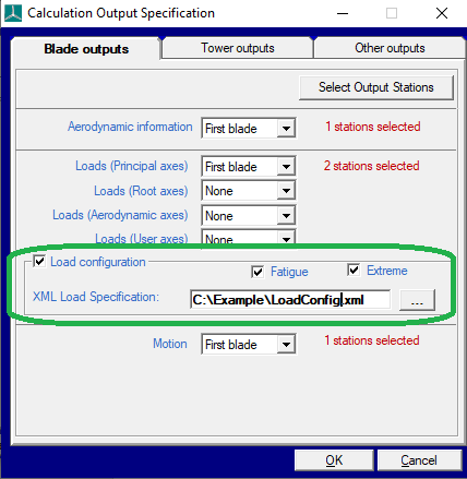
If the Extreme checkbox is also selected, customised extreme blade loads will be written to an output file with .blc filename extension.
Extreme load output files can be generated for each blade using the Additional Items option of the Specify menu and selecting Output individual blade extreme loads.
Last updated 13-12-2024