Blade Local Element Axes System
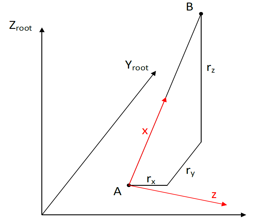
Consider a blade element with an inboard node A and further outboard node B, as shown in Figure 1.
The difference in coordinates between points A and are expressed in the Root Axes coordinates as \(r_x\),
\(r_y\) and \(r_z\), which correspond to the difference in the variables Neutral axis (x), Neutral axis (y) and
Distance along blade root Z axis respectively.
To fully define the blade local element coordinate system, two of the three vectors that form the
coordinate basis are calculated by Bladed from the user inputs.
The element coordinate system is defined as shown in red in the diagram below.
The element x direction vector is known based on the difference in positions of nodes A and B.
The local element z direction needs to be calculated to fully define the local element coordinate system for the structural model.
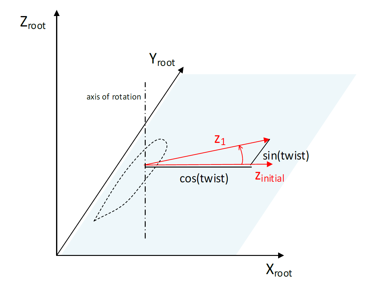
The element local z-direction vector is calculated by applying 3 successive rotations to the local element z-axis. The 3 rotations are about the blade root axes X, Y and Z directions. The element local z-axis is assumed initially to be aligned with the \(X_{root}\) direction.
Rotation due to principal elastic axes orientation
The first rotation is a rotation about an axis parallel to the \(Z_{root}\) axis.
The angle of rotation is the Principal elastic axes orientation as specified in the blade inputs screen.
This is illustrated in Figure 2.
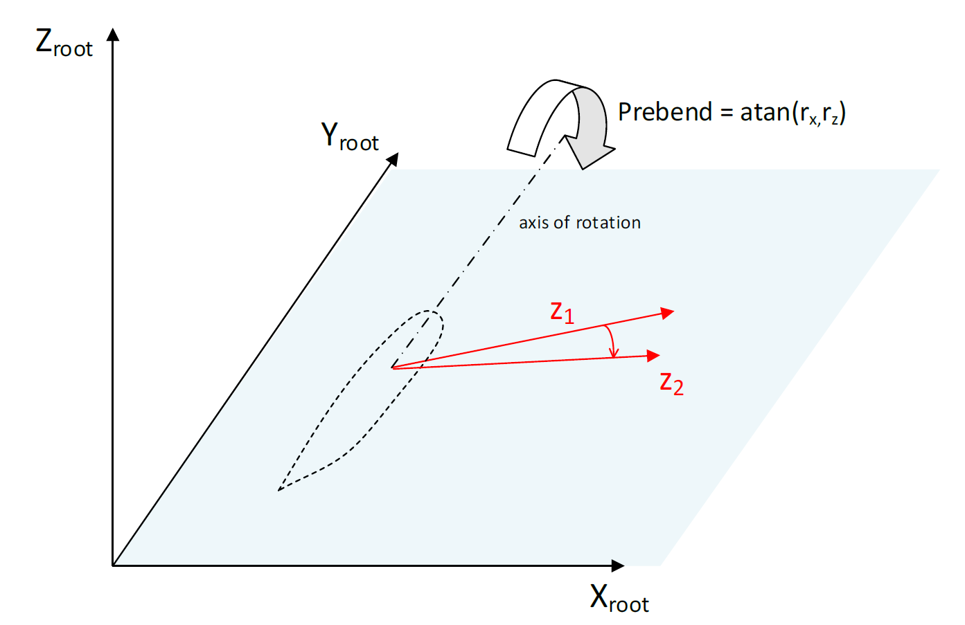
principal elastic axes orientationRotation due to prebend
Next, the vector \(z_1\) is rotated by the prebend angle, by rotating about an axis parallel to the \(Y_{root}\) axis, as illustrated in Figure 3.
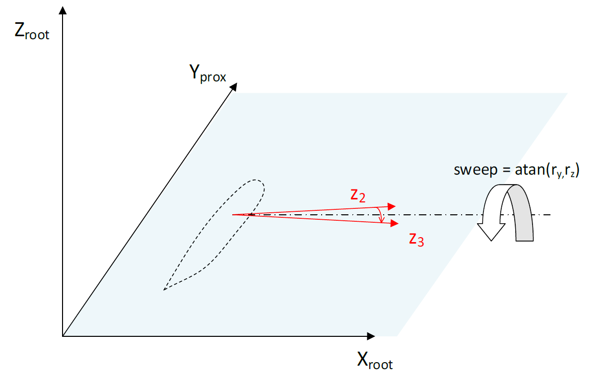
Rotation due to sweep
Finally, the vector \(z_1\) is rotated by the sweep angle, by rotating about an axis parallel to the \(X_{root}\) axis, as illustrated in Figure 4.
Last updated 13-12-2024