The variable speed pitch regulated controller
Use this control model for a turbine with a Variable Speed Generator and that has a Pitch- or Aileron-Controlled rotor. This option can be selected in the Control System window.
The variable speed pitch regulated controller
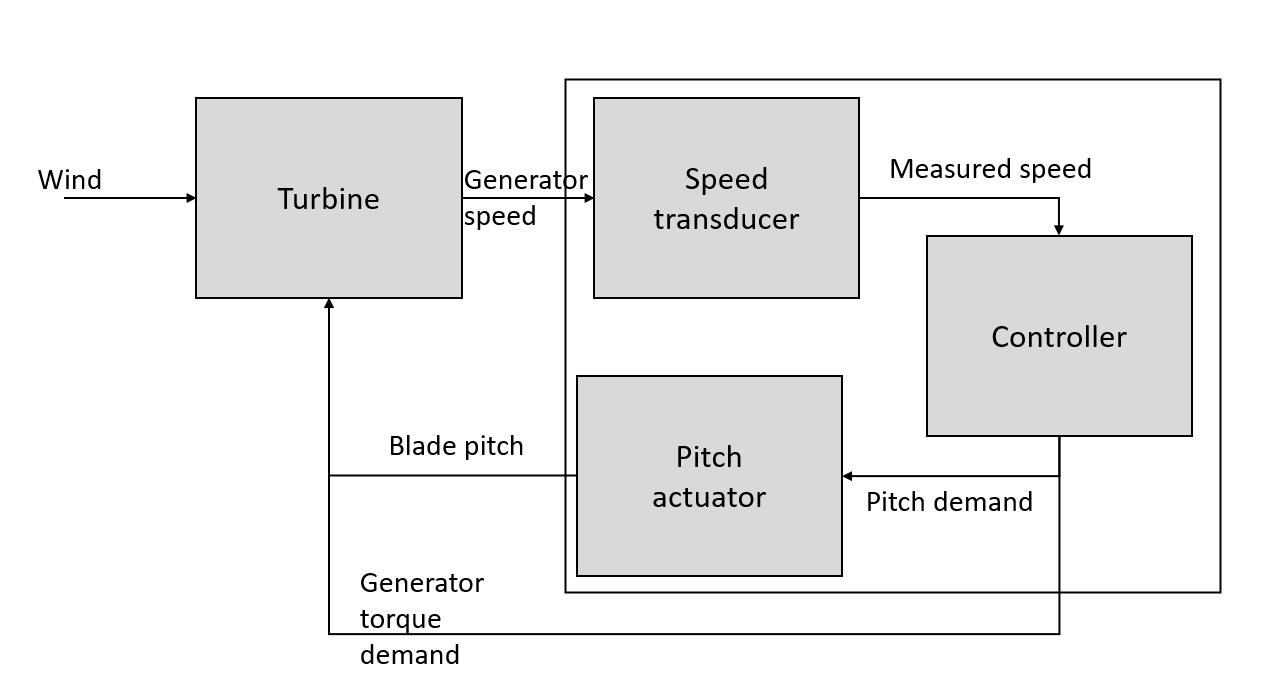
This controller model is appropriate to variable speed turbines, which employ a frequency converter to decouple the generator speed from the fixed frequency of the grid. In the full load regime pitch control is used to limit the power. The control loop is shown schematically in Figure 1.
Steady state parameters
The steady-state operating curve can be described with reference to the torque-speed graph shown in Figure 2. In the partial load regime, between points B and C, it is possible to maximise energy capture by following a constant tip speed ratio load line which corresponds to operation at the maximum power coefficient. This load line is a quadratic curve on the torque-speed plane, shown by the curve BC in Figure 2. This curve is defined using the Optimal Mode Gain which when multiplied by the square of the generator speed returns generator torque. Alternatively, a lookup table of generator torque against generator speed could be defined.
If the user selects Optimal tip speed ratio then they should input the Optimal Mode Gain parameter. Instead, the torque speed curve can be defined as a Lookup table. To add points to the table click Data and enter a lookup table of generator torque demand against generator speed, using the Add button to add entries to the table. The View button allows the curve to be visualised.
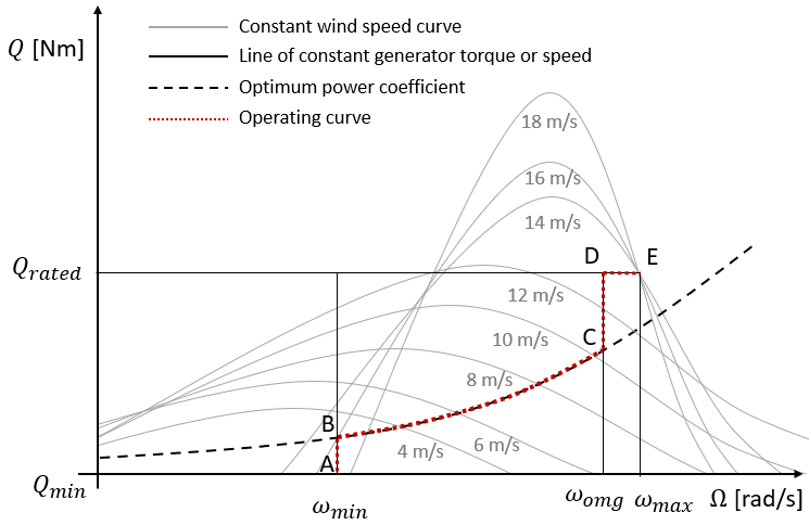
The curve BC is limited at point B by the Minimum Generator Speed and point C corresponding to the Optimal Mode Maximum Speed.
Once Demanded Generator Torque is reached at point D, the torque demand is kept
constant for all higher wind speeds. Once the Demanded Generator Speed is reached the pitch control regulates the
rotor speed. This is know as the full load regime. A small (optional) margin is allowed between points D
(where the torque reaches maximum) and E (where pitch control begins) to
prevent excessive mode switching between below and above rated control
modes. However, this margin may not be required, in which case points D
and E coincide. The line CD may collapse to a point if also desired.
In the full load regime, the blade pitch is adjusted to maintain the chosen operating point, designated E. Effectively, changing the pitch alters the lines of constant wind speed, forcing them to pass through the desired operating point.
The pitch angle is limited to the Minimum pitch angle the lower limit of pitch or aileron deployment angle. The Maximum pitch angle that is the upper limit of pitch or aileron deployment angle. There is also an option to schedule pitch angle against hub wind speed during the initial condition calculation.
The user can select between Pitch feathering or Assisted stall to specify the direction of pitching. If pitch feathering is selected, the Minimum pitch angle will be set for normal operation below rated wind speed, and the pitch (or aileron) angle will increase above rated. If Assisted Stall is selected, the maximum pitch setting is used below rated, and the pitch (or aileron) angle decreases (or moves to more negative values) above rated.
Minimum pitch angle scheduling for initial conditions
The user can schedule pitch angle against hub wind speed during the
calculation of the initial conditions. This is done by enabling the
Minimum pitch angle scheduling for initial conditions option in the
Additional items window. When active, applies to all calculation
types, both time domain and steady such as model linearisation and
steady parked loads, etc. Only overrides the value Minimum Pitch Angle
set in the Control window during initial conditions calculation. The
minimum pitch angle set by the scheduling routine may not exceed the
value set by Maximum Pitch Angle. Similarly, the scheduled minimum
pitch angle can not go above or below the pitch actuator Limit Switch.
The feature allows the user to easily specify pitch angles below rated wind speed for initial conditions. This is useful for model linearisation calculations. For above rated wind speeds, the initial condition algorithm finds a pitch angle that maintains maximum rotor speed. However, the minimum pitch angle set by the pitch scheduling routine is still used as the minimum angle even though a smaller angle might be needed to maintain the maximum rotor speed. Furthermore, it provides a convenient method for matching the behaviours in the initial condition algorithm and a time domain pitch scheduling routine implemented in a User-Defined Controller. Note that this feature only supports VSPR control strategies, and does not support the “Assisted Stall” type controller. In addition, this option only applies when the turbine is in power production mode.
The user can specify hub wind speeds and minimum pitch angles in a lookup table. During the initial condition calculation, a linear interpolation of the data points is utilized to calculate the minimum pitch angle for the current hub wind speed (both above and below rated wind speed conditions). The points in the lookup table must be in a monotonic ascending order and if the current hub wind speed is out of range of the specified lookup table the nearest value will be used.
Last updated 10-09-2024