This website uses local storage to ensure you get the best experience on our website.
Table of Contents
6 DOF Gearbox DLL Interface
The 6 Degree Of Freedom (DOF) Gearbox DLL models the gearbox, high-speed shaft and generator rotor inertia. The Bladed multibody structural components of the drive train are altered significantly when using 6DOF drive train DLL option. A free joint component called “Gearbox DLL" is added and allows the 6DOF accelerations of the gearbox component to be specified by the user. The Gearbox DLL component is straddled by the GM and GBL multibody nodes. The DLL inputs for the GM and GBL node forces and torques are in the proximal reference frame of the “Gearbox DLL” component, which is aligned with the GM node. The gearbox DLL acceleration outputs, which are calculated on initial conditions and state derivatives call types, are also with respect to the proximal reference frame. The inputs and outputs of the DLL are detailed in the tables below.
It is necessary to specify the length of the low-speed shaft and the location about which the bending is assumed. This bending point is specified as a % of the shaft length from the hub side. The stiffness and damping parameters in all 6 degrees of freedom can be specified in Power train > Transmission under the LSS Stiffness / Damping values.
On the Power Train > Mounting tab, the stiffness and damping parameters of the gearbox mounting in all 6 degrees of freedom have to be specified by clicking on the Mounting Stiffness / Damping values button. In addition the dimensions of the gearbox need to be entered by specifying the location of the LSS relative to the centre of the mounting.
The user must specify the mass and inertia of the stator in the “Mass+Inertia (stator side)” rigid body using the Added Inertias > Multibody Node Added Inertias option in the Additional Items window. Mass and inertia can be specified as either a 6×6 inertia tensor or as a scalar mass, with an offset vector from the GM node to the centre of mass, plus a 3×3 moment of inertia tensor. The specified inertia must be greater than zero in all 6 DOF, i.e. the mass, if specified, and the main diagonal elements of the inertia tensor must be greater than zero. Optionally, the “Mass+Inertia (rotor side)” component, attached to GBL node, may also be specified using the Added Inertias option in the Additional Items window.
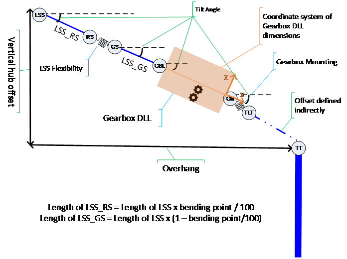
A simplified schematic of the geometry of the drive train is shown below. The positions of the nodes are related to the following parameters, which are defined in the user interface:
Overhang, Hub Vertical Offset, and Tilt Angle in the Rotor window,
LSS Length and Bending Point in the Transmission tab of the Power Train window, and
Position of GBL node relative to GM node in the Mounting tab of the Power Train window.
Figure 1: Geometry of the 6DOF drive train dll.
Functionality that is not supported or conditionally supported when
using the 6DOF Gearbox DLL is listed below:
Calculations/
Features
Compatible with
6DoF Gearbox DLL
Comments
Workaround
Modal Analysis
No
Running stand alone modal analysis
from flexibility window is not
supported. But modal analysis is
automatically completed before
commencing a simulation.
Run Modal Analysis
using a model that
does not include
6DOF Gearbox DLL
Multirotor
No
Not supported
Run using a model that
does not include 6oF
Gearbox DLL
Steady Power
Curve
No
Not supported
Implicit
Newmark beta
integrator
No
Not supported
None
Modal Analysis
No
Define initial mooting position
must be selected under
Initial Conditions
Interface Introduction
The procedure is called in different ways by Bladed, depending on the call type given by element 2 of Arg1. Arg2 always contains the time in seconds since the start of the simulation. Arg3 to Arg7 depend on the value of the call type, Arg1(2), as described below. Any arguments not mentioned are not used in that call, but must still be present.
All arguments are passed by reference, so for example Arg1 is a pointer to the start of an array of ten 4-byte integers, Arg2 is a pointer to a single 8-byte (double-precision) floating point number, and Arg4 is a pointer to an array of one-byte characters, the number of elements in the array being given by the fourth element of Arg1. The other elements of Arg1 are defined as follows:
Elements of Arg1 INTEGER array
1
To DLL
DLL interface version number.
2
To DLL
Call type: 1 to 9.
3
To DLL
Size of Arg3, intitially 4 then resized after
Initialisation call type
4
To DLL
Size of Arg4 = 2048
5
To DLL
Size of Arg5, intitially 1 then resized after
Initialisation call type
6
To DLL
Size of Arg6 = 15
7
To DLL
Size of Arg7, intitially 1 then resized after
Initialisation call type
8
To DLL
Size of Arg8 = 1024
9
From DLL
0 means OK, <0 means Abort
10
To DLL
Unique number representing the number of brakes that
have been activated. Up to 3 can be defined by the user.
The decimal brake flag is \(\Sigma_i 2^{i-1} B_i\),
where \(B_i\) is the state of each
shaft brake (0=off, 1=on).
If Arg1(9) is returned with a non-zero value an explanatory message (terminated by a null character) should be returned in Arg8.
The number of characters returned in Arg4 and Arg8 must never exceed 2048 and 1024 respectively.
The required size of the Arg3, Arg5 and Arg 7 arrays depends on the numbers of user defined states (Nx), logged output variables (Nout) and user variables (NuserVars). Arg3, Arg5 and Arg 7 are resized after the Initialisation call type and the array sizes for subsequent call types are provided in Arg1 elements 3, 5 and 7 respectively, as shown below.
Element
Post-initialisation call types
Arg1(3)
4 + Nx
Arg1(5)
Maximum of: 20, 3 + Nx + NuserVars
Arg1(7)
Maximum of: Nx + NuserVars,
7 + 2 \(\times\) Nout
Call Type 1: Initialisation
This call initialises the DLL model (using any constants which might come from the Bladed model) and returns the required number of integrator states and output variables.
Elements of Arg3 INTEGER array:
1
From DLL
Nx = Number of states to integrate
2
From DLL
Nout = Number of variables to output
3
To DLL
Nx = Number of states to integrate
4
To DLL
Nout = Number of variables to output
Elements of Arg4 CHAR*1 array
1
to
NC(max)
To DLL
Name of Parameter File and Verification File,
each terminated by a semi-colon (;). If desired
the DLL may open and read the Parameter File,
which contains any user-defined data. The
Verification File must be opened FOR
APPENDING ONLY, and can be used to keep a
record of the DLL parameters. This will be the
$VE file for the simulation, so it is
important not to overwrite the data which it
already contains. If opened, this file must
be closed again before the DLL returns.
Elements of Arg5 REAL*8 array (NR1 \(\geq\) Nx)
1
To/From
DLL
Nominal overall gearbox ratio between input and output
shaft3. If the value passed by Bladed is not
correct, the DLL should overwrite this value set Arg1(9)
greater than zero and return a message in Arg8.
Call Type 2: State Definition
This call returns the names and absolute tolerances of the integrator states required by the DLL.
This call returns the names and units of variables from the DLL to be output in time history output from Bladed (\(\bvector{y}_{out}\) from the second state-space equation \(\bvector{y}_{out} = \bmatrix{C}_{out} \bvector{x} + \bmatrix{D}_{out} \bvector{u}\)).
This call executes one step of the initial conditions iteration, and
also returns the initial values of the states (assuming everything is in
the steady state).
Elements of Arg3 INTEGER array
1
To DLL
Nx
2
To DLL
Number of DLL variables in Arg5 = 20
3
To DLL
Number of DLL output variables in Arg6 = 9
4
To DLL
0 = trial call, 1 = final call
5 to
Nx+4
From DLL
0 = State disabled; 1 = State enabled
Elements of Arg5 REAL*8 array
1
To DLL
GM node orientation - rotation vector x component5
2
To DLL
GM node orientation - rotation vector y component5
3
To DLL
GM node orientation - rotation vector x component5
This call passes the current DLL state values and any required variables derived from Bladed states to the DLL, which returns the state derivatives \(\dot{\bvector{x}}\) calculated by the DLL.
Elements of Arg3 INTEGER array
1
To DLL
Nx
2
To DLL
Nu = Number of input variables in Arg6 = 15
3 to
Nx+2
To DLL
0 = State disabled; 1 = State enabled
Elements of Arg5 REAL*8 array
1
To DLL
GM node orientation - rotation vector x component5
2
To DLL
GM node orientation - rotation vector y component5
3
To DLL
GM node orientation - rotation vector x component5
This call passes the current DLL state values and any required variables derived from Bladed states to the DLL, which returns the values of variables \(\bvector{y} (\bvector{y} = \bmatrix{C} \bvector{x} + \bmatrix{D} \bvector{u}_{in})\) that are required by Bladed.
Elements of Arg3 INTEGER array (NI \(\geq\) Nx+3)
1
To DLL
Nx
2
To DLL
Number of DLL input variables in Arg6 = 2
3
To DLL
Number of DLL output variables in Arg7 = 2
4 to
Nx+3
To DLL
0 = State disabled; 1 = State enabled
Elements of Arg5 REAL*8 array
1
To DLL
GM node orientation - rotation vector x component5
2
To DLL
GM node orientation - rotation vector y component5
3
To DLL
GM node orientation - rotation vector x component5
This call passes the current DLL state values and any required variables derived from Bladed states to the DLL, which returns the values of the output variables \(\bvector{y}_{out}\) that will be presented in the simulation time-history output.
Elements of Arg3 INTEGER array (NI \(\geq\) Nx+3)
1
To DLL
Nx
2
To DLL
Number of DLL input variables in Arg6 = 15
3
To DLL
Nout
4 to
Nx+3
To DLL
0 = State disabled; 1 = State enabled
Elements of Arg5 REAL*8 array
1
To DLL
GM node orientation - rotation vector x component5
2
To DLL
GM node orientation - rotation vector y component5
3
To DLL
GM node orientation - rotation vector x component5
This call asks the DLL whether a discontinuity has been passed. If so, the DLL has the option of specifying a particular step reduction. These calls may be ignored by the DLL if it does not model any discontinuities.
This call asks the DLL whether a discontinuity has been passed. If so, the DLL has the option of requesting a time step reduction or a step back to a particular suggested time. Bladed will not step back to a time prior to the most recent completed time step. A suggested time must be between the end of the most recent completed time step and the current simulation time. This call may be ignored if the DLL does not model any discontinuities.
Elements of Arg3 INTEGER array (NI \(\geq\) Nx+4)
1
To DLL
Nx
2
To DLL
Number of DLL input variables in Arg6 = 15
3
To DLL
0 OK
<0 request step back
-2 reuest step back to suggested time in Arg7(1)
4 to
Nx+3
To DLL
0 = State disabled; 1 = State enabled
Elements of Arg5 REAL*8 array
1
To DLL
GM node orientation - rotation vector x component5
2
To DLL
GM node orientation - rotation vector y component5
3
To DLL
GM node orientation - rotation vector x component5
This call tells the DLL that the time step is complete, so that a discontinuous change to the dynamics can be implemented if required. These calls may be ignored by the DLL if it does not model any discontinuities.
Elements of Arg3 INTEGER array (NI \(\geq\) Nx+3)
1
To DLL
Nx
2
To DLL
Number of DLL input variables in Arg6 = 15
3 to
Nx+2
To DLL
0 = State disabled; 1 = State enabled
Elements of Arg5 REAL*8 array
1
To DLL
GM node orientation - rotation vector x component5
2
To DLL
GM node orientation - rotation vector y component5
3
To DLL
GM node orientation - rotation vector x component5
This is a nominal ratio only, and is used, for example, to convert
losses defined with respect to the low-speed shaft if they are actually
applied at the high-speed shaft brake position. The actual overall ratio
may be time-varying.↩
Orientation of the gearbox mounting GM node in the global
reference frame, specified by a rotation relative to the global x axis.
This is defined by a rotation vector whose direction defines an axis, in
the global reference frame, and whose magnitude gives the angle of
rotation about this axis.↩↩↩↩↩↩↩↩↩↩↩↩↩↩↩↩↩↩
May be used by the DLL if the Bladed shaft brake position is within the scope of the DLL; the applied brake torque is calculated (as a positive number) by Bladed but the DLL may substitute a different brake model; similarly with the loss torque, which is calculated with reference to the brake position.
[^LSSTrq] Normally recalculated by the DLL; however in certain situations this cannot be done, in which case the value from Bladed can be used. This might be the case if the gearbox rotation is initially stopped by brake friction for example.↩↩
The gearbox DLL accelerations are in the proximal reference
frame of the Gearbox DLL component, which is aligned with the GM node.↩↩↩↩↩↩↩↩↩↩↩↩
May be used to share information between user-defined DLLs for
different turbine components.↩↩↩↩↩↩