Earthquakes
Including an earthquake in a simulation
Users with a licence for the Seismic module may run simulations
involving an earthquake. From the toolbar menu, select Specify\...Earthquake
to bring up the Earthquake definition screen. Select
the option to specify an earthquake to use in simulations and browse for
an earthquake file. Specify the time in the simulation at which the
earthquake will strike and the principal direction of the
earthquake.
An earthquake file is a text file containing two or three header lines and a time-history of earthquake ground accelerations. The header format is:
npoints:number of the data pointststep:time-step sizendof:number of DOFs, can be specified as 2 or 6
If the ndof field is not included then a default
ndof of 2 is assumed. The header is followed by a matrix of size
npoints (row) by ndof (column) of numbers representing the
time-history of ground acceleration.
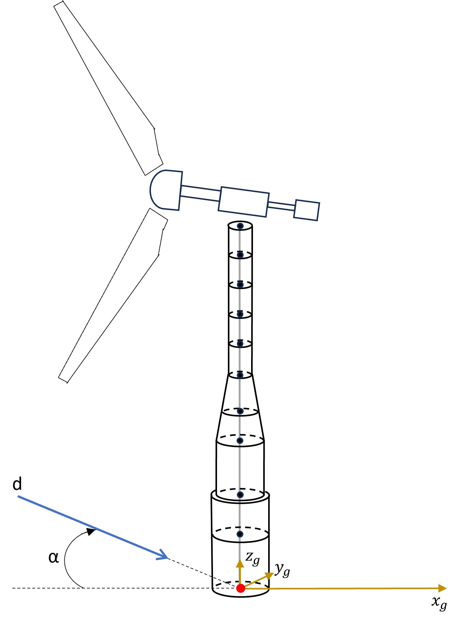
Seismic accelerations are applied in the global coordinate system. The X,Y origin for these accelerations is on the centreline of the turbine (effectively the same as the origin in the Tower screen). The Z-origin is at the ground level for an onshore turbine, or the seabed/mudline for an offshore turbine. The principal direction is measured clockwise (\(\bscalar{a}\)) from the positive global x-axis.
An important point to note is that point of application cannot be changed. Even if it's set a non-zero value for the "Z-axis origin above MWL" in the Tower screen, the seismic origin will still be as specified above.
Figure 1, displays an onshore turbine, where accelerations applied to ground level shown as red dot.
The first several lines taken from an example 2DOF earthquake file is given below. The first column of the time-history ground acceleration is the component in the principal direction and the second column is the component perpendicular to the principal direction.
POINTS 5001
TSTEP 0.01
0.021 0.016
0.062 0.019
0.124 0.037
0.187 0.056
0.249 0.074
0.311 0.093
0.338 0.127
The first several lines taken from an example 6DOF earthquake file is
given below. The first and second columns of the time-history ground
acceleration have the same definition as above. The optional third
column is the vertical component, while the fourth and fifth columns are
the two rotational components about the horizontal axes and the sixth
column is the rotational component about the vertical axis. In case that
all DOFs are included (ndof is set to 6) and the ground rotation is
not included, the three rotational components must be set to zero. Each
column must contain npoints entries.
POINTS 2000
TSTEP 0.01
NDOF 6
0 0 0 0 0 0
0.738 0 0.369 0 0 0.014
0.660 0 0.330 0 0 0.013
0.556 0 0.278 0 0 0.011
0.490 0 0.245 0 0 0.010
0.435 0 0.217 0 0 0.009
0.401 0 0.201 0 0 0.008
0.386 0 0.193 0 0 0.008
It should be noted that the inclusion of a vertical component of the ground acceleration has a certain impact on the calculation of the environmental wind and sea state. The interaction is modelled by the fundamental assumption that the body of water and air above the ground (or mudline) moves with the ground in the vertical direction, whereas the ground may still move horizontally without affecting the wind and sea state. In particular, this simplified model ensures that a vertical ground motion does not introduce any relative air or water velocity and therefore no aerodynamic or hydrodynamic loads (while vertical inertial loads are still present), whereas a horizontal ground motion generally results in aerodynamic or hydrodynamic loads (as well as inertial loads). Any effect of ground rotations is ignored in the calculation of the environmental wind and sea state, although this assumption is not valid in more extreme cases with larger ground rotations. For this reason, a warning is issued in case of non-zero ground rotation.
Generating earthquake time histories
Users with a licence for the Seismic module may generate earthquake files from a standard earthquake response spectrum. High level summary of the response spectrum compatible accelerogram algorithm is provided.
Open the Earthquake definition screen and select Generate new earthquake.
Click Import\... to start from an existing definition.
Click Define response spectrum to specify the response spectrum as a
lookup table, and then enter the following parameters:
Response spectrum damping coefficient:This is the damping coefficient of the structure for which the response spectrum is defined. The damping used in the earthquake generation is not a physical characteristic of the structure or the soil, but is the damping that was used to calculate the seismic response spectrum and as such it is inherent to the spectrum definition and it is not correct to use different damping values for the same response spectrum. It could be understood as the damping coefficient of the earthquake measuring device.Random number seed: different values will result in different earthquake realisations. However, the resulting earthquake will still match the target response spectrum selected by the user.Duration of earthquake: The length of time for which the earthquake will persist.Earthquake time step: the time step of the ground acceleration time histories which will be produced.
The accelerations will be in a given fixed direction, the principal direction of the earthquake. However, if desired, an additional component at 90º to the principal direction can be specified. This may be proportional to the acceleration in the principal direction (which simply corresponds to scaling and rotating the accelerations by a fixed amount), or independent.
Certain advanced parameters may also be specified, to control in
detail the way in which the earthquake is generated:
Accuracy of fit:the number of frequency points can be specified at which the actual response spectrum can be specified. Will be compared against the target response spectrum. The allowable deviation from the target response spectrum can also be specified.Filters:a low and high pass filter can be defined to remove frequencies outside the range of interest. This may help to speed up convergence.Shaping function:This controls the overall shape of the earthquake. Two models are included. These are typical for stiff soils or soft soils. Some seismic standards specify the length of the stationary part of the earthquake. These can be entered using theSoftoption, along with a finalDecay constant.
Unsupported Options
Bladed does not currently support earthquake simulations for floating wind turbines and support structure superelements.
Last updated 10-09-2024