Foundations
For the multi-member tower, a node can be specified as a foundation node
by clicking on the appropriate column in the nodes grid. If the entry is
left blank, there is no foundation at this node. If Rigid is
selected, this node will be rigidly connected to ground. If there are
any flexible foundation types defined, these will also be available to
choose from.
To define these foundation types, click Foundations… to open a form
which allows you to define an arbitrary number of foundation types
(corresponding to different types of rock, soil and so on). Start by creating
a named foundation type, either by clicking New, or Copy
followed by Rename. Each foundation type allows up to 6 degrees of
freedom (DOFs) if required, such as three translational and three
rotational motions. Use the check boxes provided to activate the
required degrees of freedom.
The foundation properties are defined by specifying the stiffness,
damping and mass matrices. Depending on the selected DOFs, the
appropriate matrix cells will be activated. By default, all three grids
have their lower-left diagonal greyed out, indicating that the matrices
are assumed symmetric. You can change this by clearing the All matrices symmetric check box, which will remove the greying-out (at least in the
rows and columns that have their DOFs enabled). In this mode you can
enter lookup tables or single values on both sides of the diagonal line.
For the mass matrix, enter the appropriate values for any additional
mass or inertia which moves as the foundation deflects. For the
stiffness and damping matrices, any active cell can contain either a
numerical value of stiffness or damping, implying a linear spring or
damping characteristic, or a lookup table implying a non-linear
relationship between that particular load and that particular deflection
or velocity. Use the Single value / Lookup table option buttons to
define the type of relationship for each cell. If a lookup table is
required, the cell will contain a small graph icon, and the lookup
table itself will appear in the grid provided, where it can be edited.
Non-linear Foundation Modelling
The accuracy of calculated foundation loads can be improved by selecting
the Use finite element deflections for foundation loads? option in
the Additional Items window. When this option is not selected, the
tower deflection outputs are modal deflections which give a good
estimate of overall tower motion but may not be very accurate in
calculating small deflections at support structure foundation nodes.
This can lead to a poor estimate of the foundation reaction loads.
When the Use finite element deflections for foundation loads? option
is selected, support structure foundation node deflection outputs,
during a time domain simulation, are calculated from the underlying
finite element model and used, instead of the modal deflections, to
calculate foundation reaction loads. This can improve accuracy of the
calculated foundation loads, especially for non-linear foundations.
The non-linear foundation reaction loads are calculated using finite element deflections from the previous integrator time step. Therefore, the user should check that the maximum time step is sufficiently small to provide accurate foundation load results.
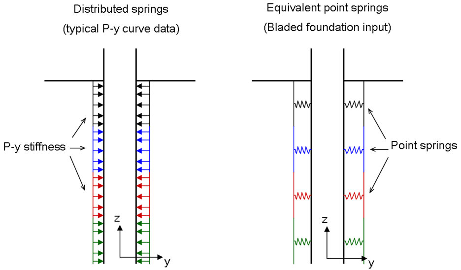
Entering P-y Curve Data in the Lookup Table
Typically, foundation data is specified as distributed stiffness \(P-y\) curves in which \(P\) = lateral resistance per unit pile length (\(\bunit{N/m}\)), \(y\) = lateral displacement (\(\bunit{m}\)). This can be interpreted as a set of ‘distributed springs’ surrounding the pile.
However in Bladed, lookup data is entered as equivalent ‘point springs’ such as pairs of lateral displacement values(m) and resistance values(N). This difference is illustrated in Figure 1.
The ‘point spring’ lookup data may already be known by the user. Alternatively, approximate ‘point spring’ lookup table data can be derived from standard ‘distributed springs’ \(P-y\) curve data. A simplified method to perform this conversion is to multiply the \(P\) values by the depth of the soil layer. The simplest situation is when each soil layer is represented by a single tower node positioned at the centre of the layer. The conversion method for this situation is shown in Figure 2
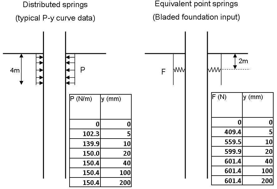
Particular care should be taken if multiple tower nodes fall within the same soil layer, or if tower nodes are positioned at a boundary between two different soil layers, rather than at the centre of a soil layer. In such situations, the conversion method would be more complex than that shown above.
When using the lookup table, Bladed calculates an initial slope in units of \(\bunit{N/m}\) based on the lookup table values (\(F/y\)). This is different to the initial stiffness (\(P/y\)) on the original \(P-y\) graph because it takes into consideration the length of pile that has been lumped into each ‘point spring’.
Lookup tables usually start from zero deflection or velocity, in which case they are assumed symmetrical about zero. If appropriate, non-symmetrical tables can be defined by entering both positive and negative values of deflection or velocity. In this case, for the diagonal terms in the stiffness matrix, it is usual that an increasing positive displacement causes an increasing positive force and an increasing negative displacement causes an increasing negative force. This ensures that the stiffnesses of the diagonal terms are positive values at all displacements (which should always be the case for a real foundation).
To display the currently-selected lookup table as a graph, click the button below the grid. The graph will also reflect your choice of linear or cubic interpolation, which you can set using the option buttons above, so that you can preview exactly what foundation characteristics will be used in load calculations. The choice of interpolation type is a global setting: it applies to all foundation definitions in the model.
In many cases, the foundation’s behaviour will be assumed to be
symmetrical in the X and Y directions. If the Symmetrical in X and Y
box is checked, whenever any additions or edits are made to one cell,
other cells are automatically changed where appropriate to maintain the
symmetry. The symmetry also means that some of the off-diagonal cells
are forced to be zero.
Note
For some of these cells, it is also theoretically possible to maintain symmetry if they are defined as lookup tables with zero initial slope; to achieve this it is necessary to clear the Symmetrical in X and Y checkbox.
Foundations are specified in the global coordinate system and do not rotate with the “X-axis clockwise from south” value.
Last updated 10-09-2024