Tower Outputs
Tower outputs such as loads and kinematics may be reported at the tower station nodes and elements of the tower.
Click Tower outputs on the Calculation Outputs Specification screen.
Tower loads may be generated at any or all of the user-defined tower members. Click Select Output Stations to determine at which stations the loads are to be output. The user should select the appropriate member from which to output loads by ticking the corresponding box in the Tower loads? column. The user must also specify load outputs required. For the loads, this can be specified independently for each of the forces and moments by selecting the option Tower moment Mx, Tower moment My and so on.
Tower deflections can also be generated for tower nodes by ticking the appropriate boxes under the Deflections? column. The user also needs to select the Tower deflections option.
Loads for Multi-Member Tower Members
Tower deflections are output in the tower base coordinate system. For multi-member towers with a rigid or linear spring foundations this aligns with the global coordinate system.
However, in case of simulations with non-linear springs, floating or simulations that include earthquakes the tower base coordinate system may not align with the global coordinate system.
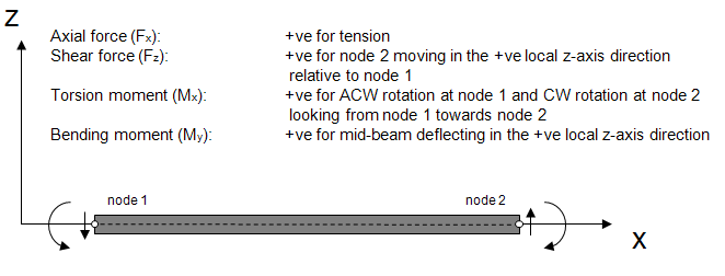
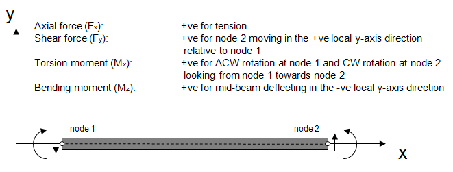
The loads are output with reference to the local member coordinate system for each member. The member x-axis is always aligned along the member. The member z axis is perpendicular to the member x-axis and aligned according to the direction cosines for the member z-axis as specified in the tower screen. These are the direction cosines of the z-axis relative to the tower base coordinate system. For example, a vertical member with z-axis direction cosine of 0.0 in the x-direction, 1.0 in the y-direction and 0.0 in the z-direction would be a member where the local x-axis corresponds to the tower base z-axis, the local y-axis corresponds to the tower base x-axis and the local z-axis corresponds to the tower base y-axis.
Multi-Member Tower Kinematics
Support structure deflections:
- Tower proximal node coordinates or in other words the tower base or modal reference node coordinates. For a fixed base turbine, this aligns with global coordinates:
- Translational deflection relative to tower base.
- Rotational deflection relative to tower base output as rotation vector1
Support structure velocities:
- Tower proximal node (tower base) coordinates.
- Translational velocity relative to tower base.
- Rotational velocity relative to tower base output as rotation vector1
Support structure accelerations:
- Tower proximal node (tower base) coordinates.
- Translational acceleration relative to tower base.
- Rotational acceleration relative to tower base output as rotation vector1
Support structure global positions:
- Global position of support structure node, in global coordinates.
- Position relative to global (0,0,0)
- Orientation relative to global coordinate system. For a fixed base turbines, all support structure nodes initially have the same orientation as the global coordinate system.
Support structure global velocities:
- Global velocity of support structure node, in global coordinates.
- Absolute translational velocity of node
- Absolute angular velocity of node
Support structure global accelerations:
- Global acceleration of support structure node, in global coordinates.
- Absolute translational acceleration of node
- Absolute angular acceleration of node
Last updated 25-10-2024
-
The rotation vector or axis-angle convention refers to the convention used to output rotation angles. This means that the rotational displacement from the undeflected orientation is considered as a single rotation about an axis. This rotation can be expressed as 3 orthogonal vectors aligned with for example the tower base coordinates. The 3 components of this rotation vector are output as the x, y and z rotational displacements.↩↩↩