Time Varying Wind
Various forms of temporal variation of wind speed and direction may be superimposed on the spatial variations described in Wind Shear and in Tower Shadow and Wake Effects.
Single point time history
A lookup table can be used to supply the wind speed and direction as a function of time, at a defined reference height. Linear interpolation between time points is used. For any particular point in space, the wind speed is then multiplied by the appropriate correction factors for wind shear, tower shadow and upwind turbine wake.
3D turbulent wind
A three-dimensional turbulent wind field can be generated, with statistical properties representative of real atmospheric turbulence. It consists of dimensionless wind speed deviations, defined as: \(\delta=(V-V_0)/IV_0\) where \(V_0\) is the mean wind speed and \(I\) the turbulence intensity, at a number of grid points on a rectangular array large enough to encompass the rotor swept area in the vertical and lateral (cross-wind) directions, and long enough in the longitudinal (along-wind) direction to allow a simulation of the desired length as the whole wind field moves past the rotor at the mean wind speed. At any point in time, the position in the longitudinal direction is calculated. The position in the lateral and vertical directions is calculated depending on the radial \((r)\) and azimuthal position \(\phi\) of any particular point on the rotor at that time, and three-dimensional linear interpolation is then used to calculate the appropriate wind speed deviation \(\delta\). The actual wind speed is then given by
where,
\(F_{s0}\) is the wind shear factor from the reference height (for mean speed \(V_{0}\) to the reference height),
\(F_{s}\) is the wind shear factor from the hub height to the point \((r,\phi)\),
\(F_{T}\) is the tower shadow factor for the point \((r,\phi)\), and
\(F_{W}\) is the upwind turbine wake factor for the point \((r,\phi)\).
IEC transients
The transient variations of wind speed, shear and wind direction defined in the international standard for the safety of wind turbine systems, IEC 61400-1, may be simulated with Bladed. Transient changes in each of the following quantities may be independently simulated, each with its own parameter values:
- Wind speed
- Wind direction
- Horizontal shear (linear variation of wind speed from one side of the rotor to the other)
- Vertical shear (linear variation of wind speed from bottom to top of the rotor)
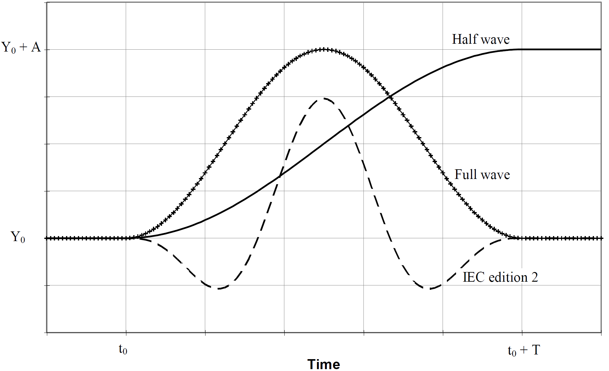
Each may be either a half-wave transient or a full-wave transient. The transients are sinusoidal, with a more complex shape defined in edition 3 of the IEC 61400-1. The parameters needed to define each transient are the starting value \(Y_0\), the start time \(t_0\), the duration \(T\), and the amplitude \(A\). These parameters are illustrated in Figure 1.
The actual wind speed at radius \(r\), azimuth \(\phi\) and time \(t\) is then given by:
where \(V_0\) is the starting wind speed at the reference height, \(V_{trans}\) is the combined effect of the wind speed and horizontal and vertical shear transients, and other parameters as defined in Implementation of transient wind in Bladed.
Implementation of transient wind
The transient variations of wind speed and wind shear are implemented in Bladed as an additional “wind increment” defined in forms of wind speed and shear changes. These are defined separately to allow all possible combinations in the wind modelling. The wind speed increment (\({\mathrm{\Delta}V(y,z,t)}^{WIND}\)) can be modelled either using simplified cosine function in Equation \(\eqref{eq:cosinegust}\) or by adopting the IEC 61400-1 standard. The latter is denoted as “IEC-2” in the user interface and user manual and given in Equation \(\eqref{eq:iec2gust}\). These two transient wind models can be formulated as:
and
respectively. Here \({\delta V}^{WIND}\) represents the amplitude of the wind speed change, measured from maximum to minimum peaks given by the user, \(t\) represents the instantaneous time and \(T\) defines the period of the transient wind. The main difference between the period characteristic in Bladed is defined as “Full”, “Half” and “IEC-2”, and is illustrated in Figure 1. For the transient wind cycle denoted as “Full”, the cycle period \(T_{c}\) is set to be equal to the transient period itself (\(T\)), while it is doubled as \(T_{c} = 2T\) for the cycle denoted as “Half” as shown in Equation \(\eqref{eq:cosinevertshear}\). The "IEC-2" version is given below in Equation \(\eqref{eq:iec2vertshear}\).
The functions adopted for the vertical shear are:
and
with \(\overline{z}\) being a non-dimensional parameter defined as \(\overline{z} = (z - z^{HUB})/D\), which depends on the hub height \(z^{HUB}\) and turbine diameter \(D\). Variable \({\delta V}^{SHEAR - V}\) represents the amplitude of the vertical wind shear change, measured from maximum to minimum peaks given by the user.
The same principle is then adopted for the horizontal shear and for the cosine function it takes the form:
and for the IEC-2 version:
with \(\overline{y}\) being a non-dimensional parameter defined as \(\overline{y} = ( - y)/D\), which depends on the lateral position \(y\) and turbine diameter \(D\). Variable \({\delta V}^{SHEAR - V}\) represents the amplitude of the horizontal wind shear change, measured from maximum to minimum peaks given by the user. Finally, all components are collected into the total contribution of the wind increment as
This way, users are able to reconstruct complex combinations of the transient effects by setting the appropriate functions in Bladed input. Despite this flexibility, IEC-2 option in the Bladed input panel is not recommended to be used for defining the vertical and horizontal shear periods since this is not in accordance with the IEC standard for wind shear transient variations.
Last updated 10-09-2024