Overview of the Multi-Rotor Functionality
A multi-rotor concept is a wind turbine that has multiple rotor nacelle assemblies (RNA) attached to a support structure. A rotor nacelle assembly consists of blades, hub, nacelle, transmission, and control system. The RNA attached to the support structure may be defined as a lattice structure or cross beams from a central monopile.
The multi-rotor user manual explains how to use the multi-rotor functionality in the Bladed. Here are the key assumptions made by Bladed.
The input definition of each RNA is identical (for example, the blade mass, geometry, control strategies, and so on). Although, during the simulation dynamic response of each RNA will be modelled separately depending on the environmental conditions and control response.
The external controller can be used to control each RNA individually.
The aerodynamic interaction between the rotors is not modelled explicitly. The induction calculation assumes one turbine, and this may not be valid for multiple rotors. In addition, the wake interaction between multiple rotors is not considered.
This document begins with how to setup a model in Bladed. The modelling options are then described along with limitations.
Setting up a Multi-Rotor Model
This section describes how to setup a multi-rotor model.
The user will have to define the structure in the Tower screen such that it can accommodate the multiple rotors. Each rotor will need to be connected to a node that is used to define the geometry of the structure.
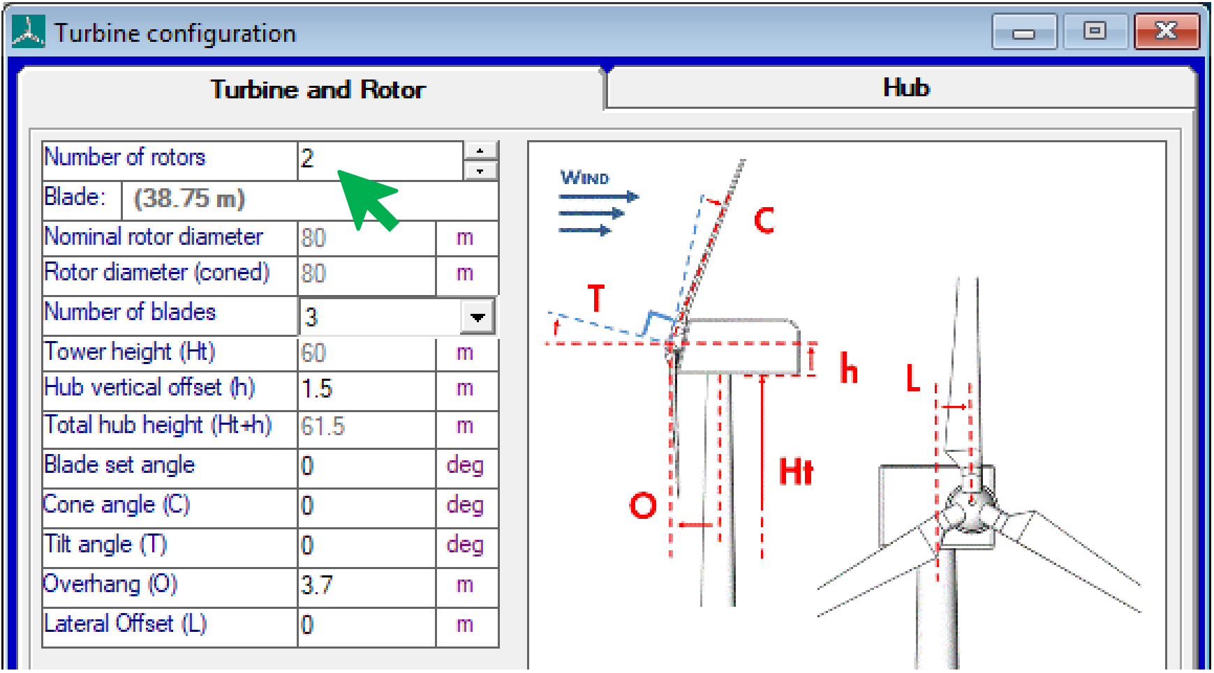
In the Bladed user interface navigate to the Rotor window. Once this
window is open increase the Number of rotors by the desired amount.
Next, open the Tower window. To use the multi-rotor functionality, it
is necessary to specify the tower geometry using the multi-member
tower option.
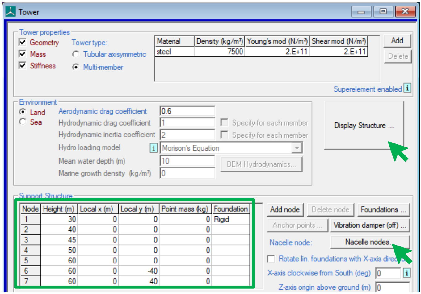
Once the structure geometry is well defined the user should specify the
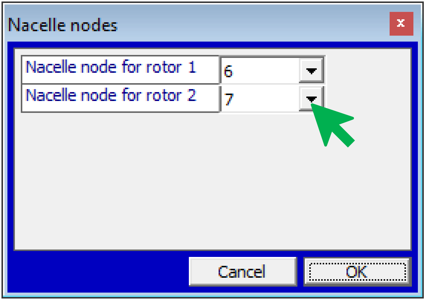
nacelle nodes for each rotor. By clicking on the Nacelle nodes... button
in the Tower screen another window will open. There will be an entry for
each rotor. The user should specify the appropriate nacelle node that
the rotor will be “connected” to.
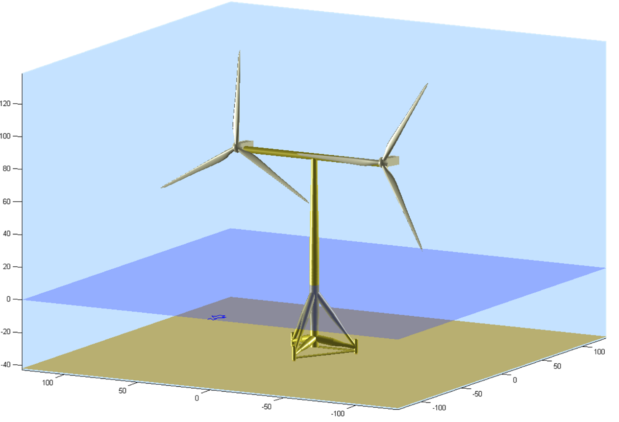
Once the edits have been completed successfully the user can check the
structure by clicking on the Display Structure... button.
After the turbine is defined, users can use Project Info data to modify simulation behaviour. Details are presented in the next section.
Modelling Options
Initial Azimuth Angle (Power Production)
By default the rotor initial azimuth angle will be \(0\) radians. This corresponds to blade 1 pointing straight upwards. Instead, the user may control the initial azimuth angle of each rotor(s). The following command may be used in Project Info. It allows the initial azimuth angle to be set per rotor. The example below is valid for two rotors. Append values to the comma separated list to make it work for additional rotors.
MSTART INITCON
NUMROTORS 2  * number of rotors
* Repeat for each rotor
INAZI 0.5 * Initial azimuth
INIMD 0   * Initial machine yaw direction
INAZI 1.5
INIMD 0.8
MEND
Rotor Rotational Directions
By default both rotors will spin in the same direction as defined in the Rotor screen. Instead, the rotational direction can be specified for each rotor. The following command can be used in Project Info. The example below is valid for two rotors. Append values to the comma separated list to make it work for additional rotors.
MSTART EXTRA
MULTIROTORDIRS C,A * Direction of each rotor (C = clockwise, A = anticlockwise)
MEND
Note that the first rotor direction in MULTIROTORDIRS must be the same
as the rotor direction specified in the UI to ensure correct elastic
axis information is passed to the UI.
Sign convention for counter-rotating rotors:
Rotor speed should generally be positive during operation. The rotor speed is defined as positive in the direction of expected rotation when operating. Rotor torque should generally be positive during operation for the same reason.
For upstream rotors, the x direction is downstream, so hub Mx is clockwise when viewed from upstream (for both clockwise and anticlockwise rotors). Rotating hub Mx should take an opposite sign for the clockwise and anticlockwise rotors.
Yaw Bearing
For single rotor turbines Bladed provides yaw bearing options to rotate the RNA. However, for multi-rotor turbines it may not be possible to rotate the RNAs individually. Due to the possibility of a blade causing a tower strike. Alternatively, a yaw bearing may be mounted midway along the tower. Then the RNAs collectively rotate with a section of the support structure.
Bladed provides the facility for users to model a Tower Base Geared Yaw Bearing in multi-rotor turbines that can be used to collectively rotate the RNAs. This is modelled within the Bladed multibody structural model. This functionality is activated via a new module written into Project Info.
Turbine Faults
This section will explain how Bladed can handle fault cases with the multi-rotor functionality.
Pitch faults can be applied to either a single or all rotors on a multi-rotor turbine. The following project info command can be used to limit the faults to any one rotor.
MSTART EXTRA
FaultOnRotorNum 2
MEND
Grid loss applies to all rotors present in the configuration. Generator short circuit fault only applies to rotor number 1, it cannot be applied to multiple rotors. In addition, fault cases can also be handled via the external controller.
Controller Options
An External controller can be used to control multiple rotors. The External controller can be set in such a way that rotors can be controlled either separately or together. The following commands can be used to distinguish between different rotors onNacelleN, ... onHubN and so on. These allow the user to obtain inputs to control logic such as rotor speed, pitch angle (and so on) and set the generator torque or pitch demands. For more information, please refer to the External Controller User Manual.
The Bladed example controller supports the simulation of multi-rotor turbines. In this case the example controller effectively simulates multiple controller instances using an identical PI control logic. One controller is created for each rotor. The controllers run in isolation and do not interact. However, the input signals such as measured rotor speed and pitch angle per rotor are supplied to each controller. The demands such as pitch and generator torque are computed per controller and applied to the corresponding rotor. As the inputs to each controller are likely different due to wind speed variations then the computed demands will be different even though the underlying controller logic remains the same.
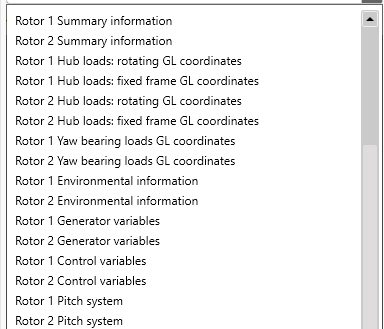
Output Groups
All output groups related to the rotor are repeated for each rotor (blade, hub, drivetrain, ...).
Defining the Wind
This section will explain how to define wind for multi-rotor structure.
While applying 3D Turbulent wind to turbines in Bladed, the lateral
centre of the turbulent field is y=0 in the global coordinate system.
However, the vertical centre depends on the option selected in the user
interface. These are Centred on Hub Height and Best Fit for Rotor and Tower.
Centred on Hub Height: The centre of the turbulent wind field is placed at hub height. In case of rotors placed in different hub heights, Bladed will automatically select the largest hub height.Best Fit for Rotor and Tower: If the turbulence field vertical dimension is less than the height of the turbine, the top of the turbulence field will be located at the height of the top of the rotor, so that the turbulence field extends as far down the tower as possible. If there are rotors at different hub heights, the turbine’s height is computed based on the rotor at the highest point. If the turbulence field vertical dimension is greater than the turbine height, the turbulence field will start at ground level and will envelop the whole turbine.
Other wind definitions such as No Variation, Single Point History, and Transients might require users to perform some geometric calculations to determine which node to match the time series in order for the hub flow speed to match the measured time series.
Unsupported Options
The BHTM module and the external interfaces such as the pitch DLL, generator DLL, and 1DOF & 6DOF gearbox DLL options are not compatible with the multi-rotor functionality and are not currently supported.
Last updated 13-11-2024