Bladed Wasim Interface
Overview
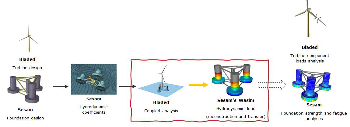
The intended use of the Bladed-Wasim interface is for structural analysis of floating wind turbines (FWTs). The overall Bladed and Sesam structural analysis workflow involves the combined use of Bladed and Sesam software tools to carry out fatigue and ultimate stress analysis on a floating turbine foundation. This interface allows a series of files that are written by Bladed to be transferred to Wasim. These files include sea state information, the reference locations from which loads and kinematics are reported, and the time series loads and kinematics. The objective of the interface is two-fold. The first objective is the time domain reconstruction of hydrodynamic loads in Wasim, based on kinematics calculated during Bladed coupled analysis and sea state information as used by Bladed. The second is to ensure that mooring line and tower interface loads transfer to Wasim, then Wasim outputs both the hydrodynamic and other loads to the structural mesh so that these can be used for structural analysis in Sesam. Figure 1 has a diagram of the Bladed-Sesam workflow and this interface is highlighted in red. See the Bladed-Wasim verification report for more details about the structural analysis workflow and verification of the interface.
This article has the following sections:
- Interface description provides details of the interface structure and the content of the output files,
- Setup Bladed-Wasim interface provides instructions on how to setup the interface in Bladed,
Interface description
Figure 2 provides an overview of the flow of information between Bladed and Wasim. The files which are exchanged are saved at the end of a Bladed time domain simulation. These files can then be read by Wasim in order to prescribe floating foundation motions and apply loads which were calculated by Bladed, and to specify the sea state as used in the Bladed simulation. The interface allows users to provide outputs from a fully coupled time domain simulation performed by Bladed, including both the floating foundation and the wind turbine. The information that is transferred by the interface is:
- Foundation kinematics.
- Tower interface loads.
- Mooring line loads at the mooring attachment locations.
- A SEA file containing the sea state information as a series of linear wave components described using frequency, amplitude, phase and direction values.
- A file providing the reference location of each node where load and kinematics are outputted in the Bladed model.
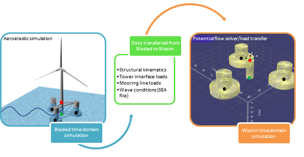
Table 1 gives a summary of the Wasim interface files which are output from Bladed.
| File number or file name | Description |
|---|---|
78, 79, 80 |
Position, velocity and acceleration respectively of the floating foundation reference node in the global coordinate system. |
76, 81 |
Tower member and mooring line loads respectively in body-fixed coordinate systems. |
RunName.SEA |
Prescribed sea state using a series of linear wave components described using frequency, amplitude, phase and direction values. RunName is the specified run name for calculation output. |
RunName.POS |
Position of nodes where kinematics and loads are output. RunName is the specified run name for calculation output. |
A more detailed description of the data that is transferred from Bladed to Wasim (see Figure 2) is described below.
Foundation Kinematics
In Bladed, the floating foundation is defined as a series of nodes and members. The Bladed-Wasim interface requires the kinematics of one node of the floating foundation to be output (an example of this node is shown in
green on Figure 2). The kinematics of this node are output in the global coordinate system and reported in Bladed output files 78, 79 and 80. These files contain time series of position, velocity and acceleration, respectively.
Note that the angular properties in those files, i.e. orientation, angular velocity and angular acceleration, are described using the Euler angle convention. Bladed output in those files is calculated using
Euler angle convention with the rotation order of Roll-Pitch-Yaw (X-Y'-Z"). The results are reported under three output groups in Bladed:
Support Structure global positions WASIM, Support structure global velocities WASIM, and Support Structure global accelerations WASIM.
See more detail in Kinematics in Euler angle frame on how Bladed outputs (Orientation, Angular Velocity, and Angular Acceleration) are transfered to Euler angle frame for Bladed-Wasim interface.
It worth noting that Wasim transfers those data to body fixed frame to solve the equation of motions. Details on transformations in Wasim are found in Wasim note on Coordinate System.
Note
In the current version of the interface, the tower node for kinematics output must be located at the origin, i.e. (0,0,0) when the turbine is in its reference position.
The reference position is the turbine initial position at the start of the simulation when there is no initial mooring displacement.
Tower interface loads
Bladed can output the tower interface load to file number 76 at one location on the wind turbine tower. The tower member must be selected by the user, as described in Setup Bladed-Wasim interface.
The loads are reported in a body-fixed coordinate system at end 1 of the member. The body-fixed coordinate system is defined as a rotation of the global coordinate system according to the orientation of the
modal reference node (tower proximal node). An example of modal reference node is shown in red on Figure 2.
Mooring line loads
In Bladed, a floating foundation must be anchored to the seabed by a series of mooring lines. For the Bladed-Wasim interface, Bladed will automatically report all mooring line loads. The loads are reported at their attachment point in the
support structure as demonstrated in black in Figure 2. They are reported in the fairlead location with same orientation of the body-fixed coordinate system as the tower interface loads. The loads are outputted to file number 81.
SEA file
If the Bladed-Wasim interface is activated, then the SEA file used during the Bladed time domain simulation is saved in the results folder alongside the other files used in the Bladed-Wasim interface. The SEA file can be read by Wasim and
used to prescribe the sea state in a Wasim simulation. See user manual section 6.12.5 for more details on the SEA file.
Node reference location file
The coordinates of the points where the loads and kinematics are being output when the turbine is in its reference position are given to Wasim. These positions are found in a file named after the specified run name for the time domain
calculation with extension .POS. To align Bladed and WASIM simulation time, the time to start writting outputs in Bladed is also written in this file. The formatting of this file is as follows:
#Kinematics (location for motion output must be at global origin when turbine in reference position)
Xk, Yk, Zk
#Tower loads (only one tower interface load output location allowed)
Xq ,Yq ,Zq
#Moorings (location of each attachment point for the n mooring lines defined in the model)
x1 ,y1 ,z1
x2 ,y2 ,z2
......
xn ,yn ,zn
#Time to start recording output (seconds)
t
For the mooring lines, the order of the node locations must match the order in which they are written in files %76 and %81.
The kinematics, loads and sea state information are prescribed into Wasim, as shown Figure 2. Further details can be found in sections 2.18.3, 2.19.3 and 2.20.2 of the Wasim user manual.
Setup Bladed-Wasim interface
The Bladed-Wasim interface is activated using the Additional Items window under the Specify menu in the Bladed user-interface, as shown in Figure 3.
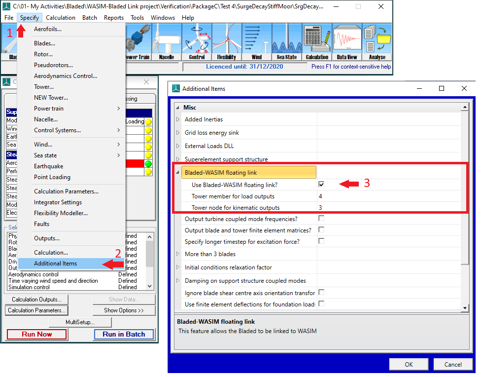
There are two parameters available to the user. Their definition is shown in the Table 2.
| Parameter | Example value | Description |
|---|---|---|
Tower member for load output |
4 | Index of the tower member from which load output will be generated. The loads will be output from End 1 of the selected member. |
Tower node for kinematic outputs |
3 | Index of the node at which kinematic outputs will be generated. The selected node must coincide with the global origin when the turbine is in its reference position. |
The following limitations should be considered when using the interface:
- These values should be a positive (non-zero) integer number.
- Tower member index should not be greater than the total number of
tower members. - Tower node index should not be greater than the total number of
tower nodes. - Tower load is output at
end 1of the specifiedtower member. - In the current version,
Tower nodefor kinematics output must be located at origin, i.e. (0,0,0). - This feature only intended for use with offshore module and advanced offshore module.
Note
To ensure that tower member loads are correctly output for this link, end 2 of the tower member should be positioned above end 1 (the local member x-axis needs to be pointing upwards).
Note
The user must ensure that the WASIM model settings align with the Bladed configuration for BEM loading correction, particularly regarding the BEM yaw adjustment and excitation phase drift.
Last updated 11-12-2024