Definition of Wind and Nacelle Direction
The wind direction is the direction from which the wind is coming, measured clockwise from North when looking from above, i.e. East of North.
The default nacelle orientation and the wind direction together define the yaw misalignment. The yaw misalignment is illustrated in Figure 1 for an upwind rotor and in Figure 2 for a downwind rotor. The yaw misalignment may change during a simulation if any Yaw Control is specified, i.e. passive yaw, active yaw control or a yaw maneuver. Note that the yaw angle can also be defined explicitly for the steady parked loads calculation.
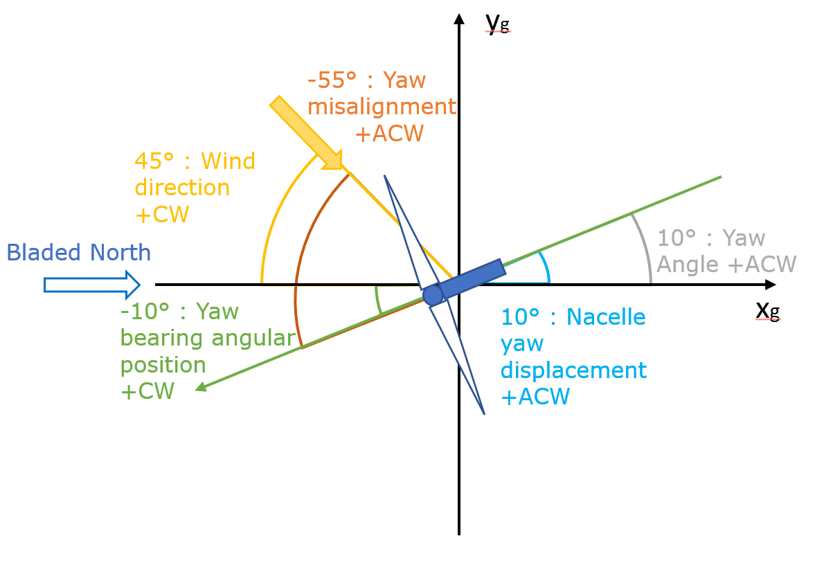
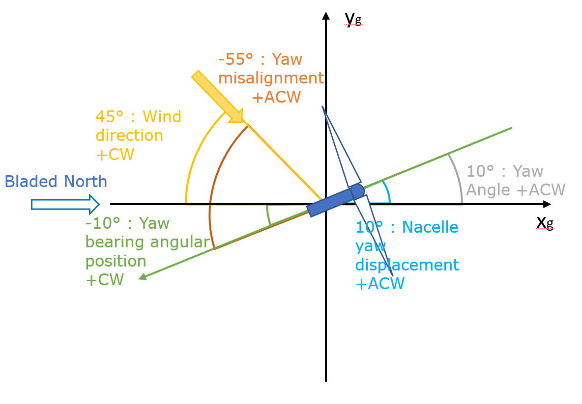
In addition to the wind direction, the definitions of the nacelle orientation and yaw misalignment are as follows:
Nacelle yaw displacement from Nacelle Motion output group. This is measured anticlockwise from the global coordinate system \(x_g\) axis. This is wrapped to lie between +-180$\degree$.
Yaw angle from Structural State Positions output group (structural state position). Measured anticlockwise from positive tower top local coordinate system x-axis. This aligns with global x-axis if tower is undeflected. This angle is unwrapped.
Yaw bearing angular position from yaw actuator output group. This is measured clockwise from North analogous to the wind direction. This angle is unwrapped. Matches the definition of the initial nacelle angle.
Yaw misalignment from summary info output group is the negative value of the yaw error between nacelle yaw displacement and wind direction. The yaw error is calculated as the sum of the wind direction plus nacelle yaw displacement modulo 360$\degree$ and is the anticlockwise direction measured from the wind direction. As the yaw misalignment is the negative of the yaw error it is the clockwise angle measured from the wind direction and is limited to the range +-180$\degree$.
Last updated 15-11-2024