Yaw Control
If using the yaw modelling options defined in Yaw Control accessible by the Control window then the yaw bearing is represented by a single rotational degree of freedom
called a “hinge” as shown in the Turbine Multibody Diagram.
Where the yaw bearing connects to the tower depends on the tower modelling option selected by the user in the Tower screen. If using the monopile (axisymmetric) tower then the yaw bearing connects directly to the tower top corresponding to the highest tower station. If using the multi-member tower option then a single or multiple nacelle node(s) can be specified by the user depending on whether a Multi-Rotor Turbine will be simulated. Regardless of the number of nacelle nodes a yaw bearing will be added to each tower node connecting each rotor nacelle assembly to the tower at the desired locations.
These models are relatively simplistic and can be used to prescribe simple yaw maneuvers. For a more detailed yaw system model the user may want to consider a Flexible Geared Yaw Bearing option that is also available.
Yaw Dynamics
The user can select the following options related to the yaw bearing dynamics:
None: The nacelle direction will remain fixed relative to the tower top.Rigid Yaw: The nacelle follows the demanded nacelle angle precisely. During yaw manuevers the acceleration of the hinge degree of freedom is prescribed. This means that the acceleration is calculated and then imposed on the structural model.Flexible Yaw: The nacelle yaws passively with respect to the demanded nacelle angle as a result of aerodynamic forces. During yaw manuevers, yaw motion is achieved by applying equal and opposite torques across the hinge degree of freedom, to represent the torque applied by a yaw actuator.Controlled Torque: The Yaw Actuator Torque is specified by the external controller.
If an option other than None is selected then the Constant Friction input can be specified by the user. The nacelle will only start to yaw if the balance of applied yawing torques at the yaw bearing bearing exceeds the friction plus the stiction torque, and it will stop yawing if the balance of torques falls below the friction torque. The applied torques include aerodynamic and inertial Mz torque and either the spring/damper torque (in the case of Flexible yaw) or the Controlled Torque. In the case of Flexible Yaw the user can also specify Additional Stiction.
Active Yaw
Three choices are available for defining the demanded nacelle angle in simulations:
None: The demanded nacelle angle will be fixed at at the initial angle. The default is zero such that an upwind turbine is pointing North (negative global \(x_g\) axis). The initial angle can be modified inCalculation Parameters > Initial Conditions.Prescribed Maneuver: Specify a yaw maneuver by enteringTime to Start Yaw Maneuverwhen the demanded nacelle angle starts to move. TheRequired yaw positionis the nacelle demanded angle at the end of the yaw maneuver. And theYaw rate for yaw maneuversis the demanded yaw rate to be used throughout the maneuver.External controller: IfRigid YaworFlexible Yawis selected, the user-defined controller will generate a yaw rate demand which defines theDemanded Nacelle Angleat any instant. This will initiate a Yaw Maneuver during a time domain simulation. IfControlled Torqueis selected, the user-defined controller will generate a yaw actuator torque demand. This is assumed the same as the actual yaw actuator torque. Since the dynamic response of the yaw torque actuator is assumed to be fast and is therefore not represented in the model.
Flexible Yaw Modelling Options
If Flexible Yaw is selected, specify the either the Linear Spring or Hydraulic Accumulator.
if using the Linear Spring option then specify the Yaw Damping and the Yaw Stiffness. Note that using the external controller, it is possible to control the yaw damping and stiffness and also to provide additional friction by applying a yaw brake torque.
The following parameters are required to model yaw compliance provided
by a Hydraulic Accumulator system:
Gas Volume: The volume of gas in the accumulators \(V\).Nominal Pressure: The equilibrium pressure in the hydraulic system \(P\).Pump Flow per Unit Yaw: The volume of fluid \(F\) which must pass through the yaw motor to achieve a one radian change in nacelle angle.Yaw Torque per Unit Pressure: The relationship between the pressure difference \(Q\) across the yaw motor and the torque developed at the yaw bearing.Gas Law Constant: The constant \(\gamma\) for the gas in the accumulator.
The following formulae are used to determine the yaw torque \(T\), starting with the gas law equation
where the user can specify \(\gamma = 1\) for isothermal conditions.
The yaw torque \(T\) provided by the hydraulic system is then given by:
where \(v_1 = V - F \alpha\), \(v_2 = V + F \alpha\), and \(\alpha\) is the difference between the actual and the demanded nacelle angle.
Yaw Maneuvers Explained
The following sections explain what happens in Bladed when a user specifies yaw maneuvers when using either the Rigid Yaw or Flexible Yaw options.
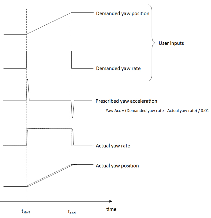
Rigid Yaw
For Rigid Yaw, the acceleration of the hinge degree of freedom is
prescribed. This means that the acceleration is calculated and then
imposed on the structural model. The acceleration is calculated by
considering the difference between the demanded yaw rate and the actual
yaw rate. This is illustrated for a yaw "prescribed maneuver" below.
The actual yaw rate and position result from integrating the yaw acceleration at each time step. The actual yaw rate and position will lag slightly behind the demanded yaw rate and position.
The yaw actuator torque \(T\) is calculated according to the following relationship
where \(M_z\) is the yaw bearing torsion load and \(Q\) is the friction.
For the case of Rigid Yaw without a prescribed maneuver, the demanded
yaw position will be equal to the initial yaw position (usually zero).
If the yaw drive starts to move due to applied forces, a prescribed yaw
acceleration will be calculated to bring the yaw drive back to its
original position.
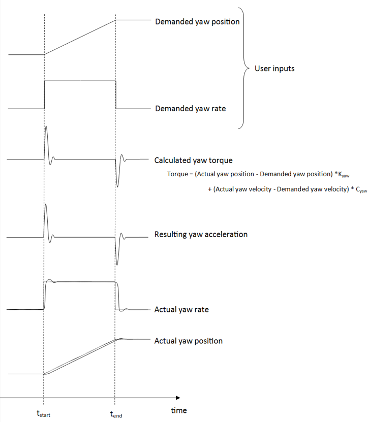
Flexible Yaw
For Flexible Yaw, the demanded yaw position and rate are again
specified by the user. These demanded values are compared to the actual
values and used to calculate the torque to apply across the hinge,
according to yaw drive stiffness and damping.
where \(\theta\) is the measured yaw position, \(\theta_d\) is the demanded yaw position, \(\dot{\theta}\) is the measured angular velocity, \(\dot{\theta}_d\) the demanded angular velocity \(K_{\text{yaw}}\) is the yaw stiffness and \(C_{\text{yaw}}\) the yaw damping.
The torque applied across the hinge causes an acceleration in the hinge.
For the case of Flexible Yaw without a specified yaw maneuver, the
demanded yaw position will be equal to the initial yaw position (usually
zero). If the yaw drive starts to move due to applied forces, a a yaw
torque will be calculated and applied to bring the yaw drive back to its
original position.
Last updated 30-08-2024