Upwind Wake Modelling Options
There are two ways to model a wake originating from an upwind turbine in Bladed:
The upwind turbine wake tab in the
Wind Statescreen.The dynamic upwind wake screen in
Specify > Wind > Upwind turbine wake
From these options, the latter is recommended for site-specific calculations as the user-inputs in general do not need to change between runs in a set of site-specific load calculations, because they are independent of operating condition. The former has several user entries relating to the upwind turbine (e.g. tip speed ratio), which are dependent on operating condition. This formulation will be deprecated in a future release.
Gaussian wake
To define simple, static Gaussian wake, this must be done in
the Upwind turbine wake tab, where the user must enter:
Centre line velocity deficit: as a percentage of the local wind speed.Wake half-width: the distance from the wake centre line at which the deficit is reduced to \(\exp(-0.5)\) times the centre line value.
Meandering wake
The Dynamic upwind wake screen allows the user to generate a wake at the start of the simulation based on an eddy-viscosity model and also meander the wake centreline throughout the simulation.
The wake deficit profile is calculated at the start of the simulation and is constant throughout. The user must provide a steady operational loads relevant to the upwind turbine over all operating points. The initial wake profile is calculated from the axial induction factors of the aerodynamic information group in these steady operational loads results at the wind speed that corresponds to the mean wind speed of the current simulation. It is therefore important that aerodynamic information is output at every blade station otherwise the initial wake profile will be very coarse. This information can also be obtained from an aerodynamic information simulation but then the information will not be valid for multiple wind speeds.
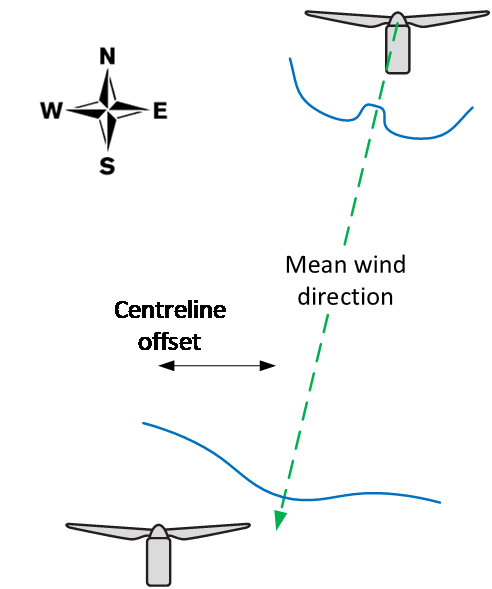
The initial wake profile is propagated downstream according to the thin shear layer approximation of the Navier-Stokes equations, which is documented in the theory manual. The distance of propagation and the eventual centreline offset at the modelled turbine is determined by the relative global location (North and West) of the upwind turbine and the simulation mean wind direction, which is shown as an example in Figure 6‑1.
 |
|---|
| Figure 1: Propagation of a wake profile from upstream turbine to modelled turbine. |
There is also the option for a upwind meandering wake where the wake centreline meanders throughout the simulation. The motion of the wake is calculated by integrating the lateral and vertical components of a user-specified turbulence file. This turbulence file should be low-pass filtered in order to avoid high frequency content in the meandering.
Generating low-pass filtered wind file
When an upwind turbine wake model (either Gaussian or Eddy viscosity) is chosen in Bladed then the wake centreline is fixed throughout the simulation. The meandering wake model allows the “meandering” of the wake centre-line with simulation time. In order to do this, the user must firstly generate a bespoke low-pass filtered wind file, separately to the normal wind file used in turbulent wind simulations.
Use the following Project Info option while Generating a Wind File to apply a low-pass filter to the turbulent velocities. The filter is applied to the velocity signal in the longitudinal direction for each velocity component at each (y,z) grid point.
MSTART EXTRA
CUTOFF 1 \* Activate low-pass filter (1 = sharp cut-off)
CutoffFreq 0.04 \* sharp cut-off frequency for turbulence spectrum in Hz
MEND
Note that a low-pass filter cannot be applied to:
A wind file generated using the Mann turbulence model.
A wind file generated to match a wind time history at specific (y,z) grid node in the file.
Last updated 30-08-2024