Blade Section Property Coordinate Systems
The blades in Bladed are defined as a finite series of 2D sections along the blade's span, using the neutral axes system relative to the blade root axes system.
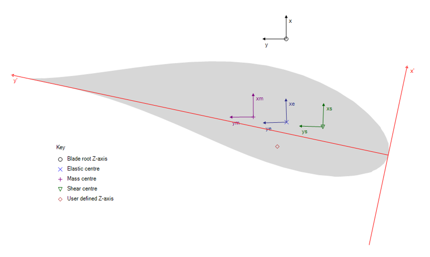
Each section has an aerofoil that is oriented according to the Aerodynamic twist, with an associated chord axes system origin located at the leading edge as shown in Figure 1. The aerofoil must be positioned relative to the neutral z-axis, which passes through the elastic centre of each blade section.
This is done by defining the location of the elastic centre as a percentage of the Chord length, measured from the aerofoil leading edge along the chord axes that follow the Aerodynamic twist:
Elastic centre (x')Elastic centre (y')

Details on the orientation of the local element frame relative to the blade root axes can be found in Blade Local Element Axes.
Each section then allows for the definition of additional property systems that describe the structural and aerodynamic properties of the blade.
Note
Not all coordinate systems are relevant in every model; their inclusion depends on the model's complexity.
For example, the principal shear axes coordinate system is not needed if Shear stiffness is omitted.
| Coordinate System | Description |
|---|---|
| Root axes | Fixed to the blade root, and it does not rotate with twist or blade deflection but rotates about the z-axis with pitch. |
| Chord axes | Located at the leading edge of the aerofoil and follows the Aerodynamic twist. |
| Principal elastic axes | Located at the Elastic centre and follows the Principal elastic axes orientation (xe, ye). |
| Principal shear axes | Located at the Shear centre and follows the Principal shear axes orientation (xs, ys). |
| Principal inertia axes | Located at the Mass centre and follows the Principal inertia axes orientation (xm, ym). |
| User axis | Located at the User axis, specified by the user for additional loads output. See Loads Outputs at User Axes for details. |
Definition of Centre Locations and Axes Orientations
The centres, including the Elastic centre, Shear centre, Mass centre and User axis, are all defined with respect to the chord axes, which are controlled by the Aerodynamic twist.
The locations of these centres are specified as a percentage of the chord length measured from the aerofoil leading edge.
An example of this is illustrated in Figure 3 for the Shear centre definition.
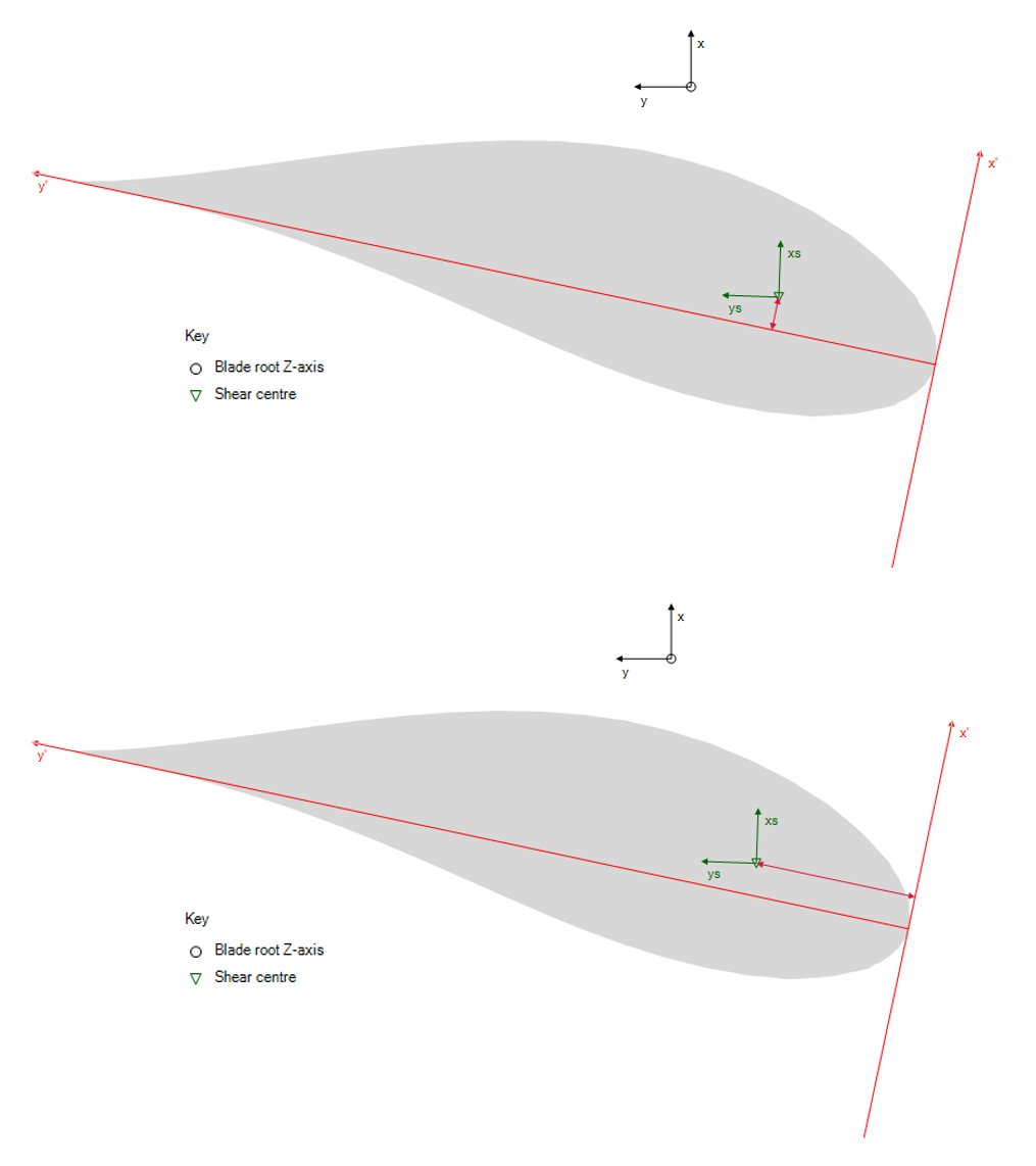
Shear centre (x'). Bottom: Definition of Shear centre (y').Furthermore, the orientations of the Aerodynamic twist, Principal elastic axes orientation (xe, ye), Principal shear axes orientation (xs, ys), and Principal inertia axes orientation (xm, ym) are all defined with respect to the root axes and are positive in the clockwise direction as shown in Figure 4.
In the GUI, the unit of the inputs is in degrees, whereas in the project file, it is in radians.

Overview of Blade Section Inputs and Associated Coordinate Systems
This section provides an overview of the structural properties defined in the various coordinate systems. For more details, see Blade Section Stiffness and Blade Section Mass.
Principal Elastic Axes
The following blade section input properties are defined in the principal elastic axes coordinate system:
Bending stiffness about xeBending stiffness about yeShear stiffness along xeShear stiffness along yeAxial stiffnessFlapEdgeCStiffTorsionFlapCStiffTorsionEdgeCStiff
Principal Shear Axes
The following blade section input property is defined in the principal shear axes coordinate system:
Torsional stiffness
Principal Inertia Axes
The following blade section input properties are defined in the principal inertia axes coordinate system:
Mass/unit lengthPolar mass moment of inertia/unit lengthRadii of gyration ratio
Chord Axes
The following blade section input properties are defined in the chord axes coordinate system:
ChordThicknessFoil section
Last updated 16-12-2024