Dynamic Control Logic in Bladed Example Controller
The Bladed Example Controller (herein referred to as the Example Controller) is a discrete time controller. The Example Controller can be used to simulate both pitch regulated and variable speed turbine concepts. It uses the External Controller API to obtain input parameters, access measured signals and set controller demands. The Example Controller can be used "out-of-the-box" or edited by the user to integrate more complicated control features into dynamic simulation.
At runtime the controller will read in various parameters to detect what control strategy to use and then set demands based on a set-point defined by user inputs. It can automatically detect the control strategy set by the user in the Control window. In addition, parameters such as generator speed limits, pitch angle limits, optimal mode gain and so on are automatically read. Based on the control strategy, parameters and limits PI closed loop control logic is applied to set a demand based on measured signals to meet a particular set-point. The gain and gain schedule that govern the PI control logic are read automatically from additional parameters and can be edited by the user.
The Example Controller implements logic for the following control strategies:
Note
If pitch control loops are used then the example controller will automatically detect the following:
- The pitch actuator input demand as being either pitch angle or rate demand based on the definition of the Pitch System.
- Whether the blade pitches to feather or to stall.
PI control implemented in the Example Controller
PI or Proportional plus Integral controllers are used for closed loop controllers on turbines. A PI controller with input \(x\) and output \(y\) has the form:
where \(K_p\) is the proportional gain, \(K_i\) is the integral gain.
The input \(x\) is the deviation of a measured quantity from its desired level or set-point. The output \(y\) is the demanded control action, which is intended to minimise those deviations.
Various control design techniques are available to help with the selection of the gains \(K_p\) and \(K_i\). The main aim is usually to minimise deviations from the set-point without excessive control action and without causing any instabilities. A non-zero integral gain is important to ensure that the steady-state error is zero. This means that the measured quantity settles at the desired value in steady state conditions. The ratio \(K_p/K_i\) is known as the integral time constant.
Instantaneous desaturation is used to prevent "integrator wind-up" when the output \(y\) is constrained by limits.
Gain scheduling implemented in the example controller
The gains of a closed loop controller such as a PI controller are designed to give good control (stable operation with good tracking of the set-point) at one particular operating point, for example at one wind speed. At a different operating point, the gains may need to be modified because the relevant characteristics of the system may be different. This is particularly true of pitch controlled turbines, where the aeroydnamic gain changes significantly with pitch angle, and hence with wind speed.
The gain scheduling facility allows the overall gain of each PI
controller to be modified as a function \(f(V)\). In the case of the
Example Controller the variable \(V\) may be either the pitch angle,
electrical power, wind speed or generator speed. The actual
proportional and integral gains at any point are
given by \(K_p/f(V)\) and \(K_i/f(V)\), where \(K_p\) and
\(K_i\) are the proportional and integral gains. These are entered in
Additional Controller Parameters.
Variable Speed Pitch Regulated
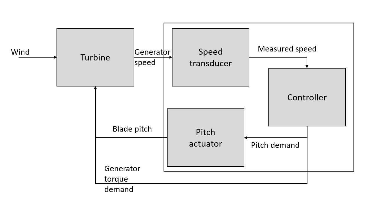
Figure 1 shows the operating curve used to generate pitch and torque demands. The torque demand loop is active during partial load regime, and the pitch demand loop in the full load regime. The control loop is shown schematically in Figure 2.
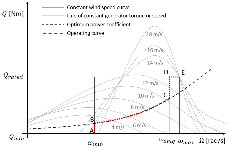
In the partial-load regime this controller varies the generator torque demand to regulate the speed of the
generator and rotor. The input \(x\) is the deviation of the generator speed from the set-point and the output \(y\) is the demanded
generator torque. The speed set-point switches between \(\omega_{min}\) and \(\omega_{omg}\). In low winds it is at \(\omega_{min}\), and
the torque demand output is limited to a maximum value given by the optimal tip speed ratio curve BC. This
causes the operating point to track the trajectory ABC. In higher
winds, the speed set-point changes to \(\omega_{omg}\), and the torque demand output is
limited to a minimum value given by the optimal tip speed ratio curve,
causing the operating point to track the trajectory BCD, and a maximum
value of Demanded Generator Torque. In this regime the pitch angle is set to either the Minimum Pitch Angle or Maximum Pitch Angle
angle dependent on whether Pitch to Feather or Assisted Stall has been selected.
Note
The Example Controller does not support Pitch Scheduling.
In the full-load regime, the torque is held constant at the Demanded Generator Torque \(Q_{rated}\) and the speed is then
controlled by adjusting the blade pitch angle. The input \(x\) is the devaiation of measured generator speed from the maximum
generator speed Demanded Generator Speed (\(\omega_{max}\)) while \(y\) is the pitch angle/rate demand. On the operating curve
this corresponds to reaching point E where the pitch control loop becomes active when the speed exceeds \(\omega_{max}\) Demanded Generator Speed.
Fixed Speed Pitch Regulated Control
The Bladed example controller varies the pitch angle above rated, to regulate the electrical power output to the set point given. This is done using PI closed loop control to set the demanded pitch angle/rate.
The input to the controller is the deviation of measured power from the set-point. The output demand set by the example controller is either a pitch angle or rate demand.
Variable Speed Stall Regulated
This controller varies the generator torque to regulate the speed of the generator and rotor. Above rated, the power can be controlled by adjusting the speed set-point to stall the rotor. The operating curve is shown in Figure 3
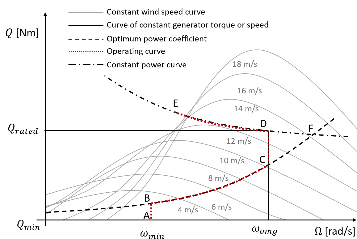
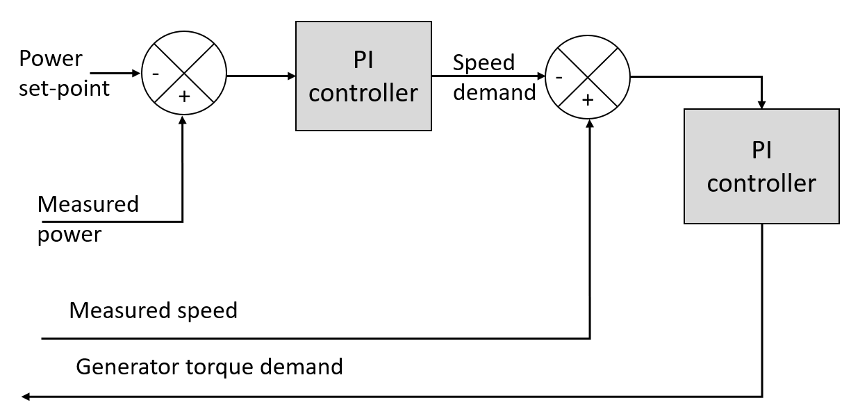
Two closed loop control loops are used for the generator torque control, as shown in Figure 4. An inner control loop calculates a generator torque demand as a function of generator speed error, while an outer loop calculates a generator speed demand as a function of power error.
Below rated, the speed set-point switches between \(\omega_{min}\) and \(\omega_{omg}\). In low winds it is at \(\omega_{min}\), and the torque demand output is limited to a maximum value given by the optimal tip speed ratio curve BC. This causes the operating point to track the trajectory ABC. In higher winds, the set-point changes to \(\omega_{omg}\), and the torque demand output is limited to a minimum value given by the Optimal Tip Speed Ratio Curve, causing the operating point to track the trajectory BCD. Once the torque reaches \(Q_{rated}\), the outer control loop causes the speed set-point to reduce along DE, and the inner loop tracks this varying speed demand.
Last updated 28-08-2024