Coupled Mode Animator
The coupled mode animator enables 3D visualisations of the coupled modes represented within the Campbell diagram, allowing engineers and analysts to explore system behaviour and stability more effectively.
For each operating point and coupled mode a unique output is created that can be read and animated by the Bladed Results Viewer.
The Campbell diagram calculation, found under Model Linearisation in the Steady Calculations options, will generate the coupled mode animation outputs if the Output coupled mode animations data option is enabled in the Campbell diagram screen.
Encrypted turbine components may restrict data access, and prevent the output of coupled mode animation.
Note
Users can also independently execute the tool via command line on Campbell diagram results produced by Bladed.
Visualising Coupled Modes
The theory behind calculating coupled modes is described in the article Calculating Coupled Modes. A three-dimensional animation can be used to visualise the coupled mode kinematics of the structure derived from superimposing uncoupled modes. The uncoupled modes vary sinusoidally as per the phase, shape and amplitude contribution to the coupled mode as determined by the Campbell diagram calculation. Every contribution is then scaled by a unique scale factor to ensure the deflections are easily visible. The rotor azimuth is incrementally increased for each time step in the animation, based on the steady-state rotor speed. The animation of the rotor rotation can be disabled using Command Line with Arguments, which also allow for adjustment of the scaling factor.
Animation Duration
The duration of the animation depends on the period of the coupled mode (\(T_m\)), and the period of a rotor rotation (\(T_r\)). If \(T_m>T_r\), the duration will be \(T_m\); otherwise, it will be \(T_r\). The animation time step is fixed at \(\frac{T_m}{50}\), regardless of the animation’s duration, to ensure a high resolution of the resulting mode animation.
However, this can lead to excessive data points for higher-order coupled modes, as \(T_m\) is often orders of magnitude smaller than the \(T_r\). To minimise the amount of animation data, an animation duration of \(T_r\) will only be used for coupled modes with mode orders of 3 or lower. This value can be change via Command Line with Arguments using the modeOrderThresholdToOutputFullRotation argument.
Note
If excludeSteadyStateRotorSpeed is enabled or if the rotor speed is zero, animation data will be only be generated for the duration of \(T_r\).
Coupled Mode Animation Output Data
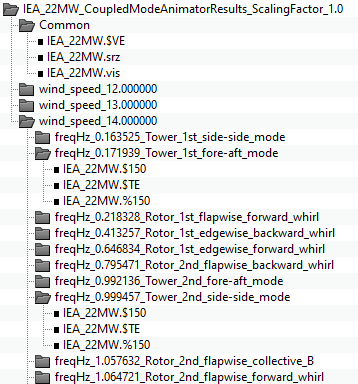
The coupled mode animation data will be generated and saved in a dedicated folder alongside the standard outputs. This folder will organise the different operating points such that each operating point (wind speed) will have its own folder. Each operating point folder, in turn, will have a subfolder for each of the coupled modes, organised by frequency and coupled mode name.
An example output for a Campbell diagram run is shown in the figure below for the shipped demo model found in <Bladed installation dir>/DemoModels/IEA_22MW.
Each coupled mode has two unique files, which are the structural state header .%150 and data .$150 files, whereas the verification file .$VE, serialisation file .srz and visualisation file .vis are common for all coupled modes in all operating points. The termination file .$TE is also common, but is the file that needs to be selected when viewing a single coupled mode in the Bladed Results Viewer, and is therefore present in the output folder for each coupled mode. If copying coupled mode outputs to another location, be sure to copy the Common folder too, as this is needed for result animation.
Viewing Coupled Mode Animations in Bladed Results Viewer
3D animations of the coupled modes can be viewed in the Bladed Results Viewer that is available on the Bladed user portal under Bladed Downloads. The Bladed GUI also has capabilities to view coupled modes, but the recommended workflow is using the results viewer.
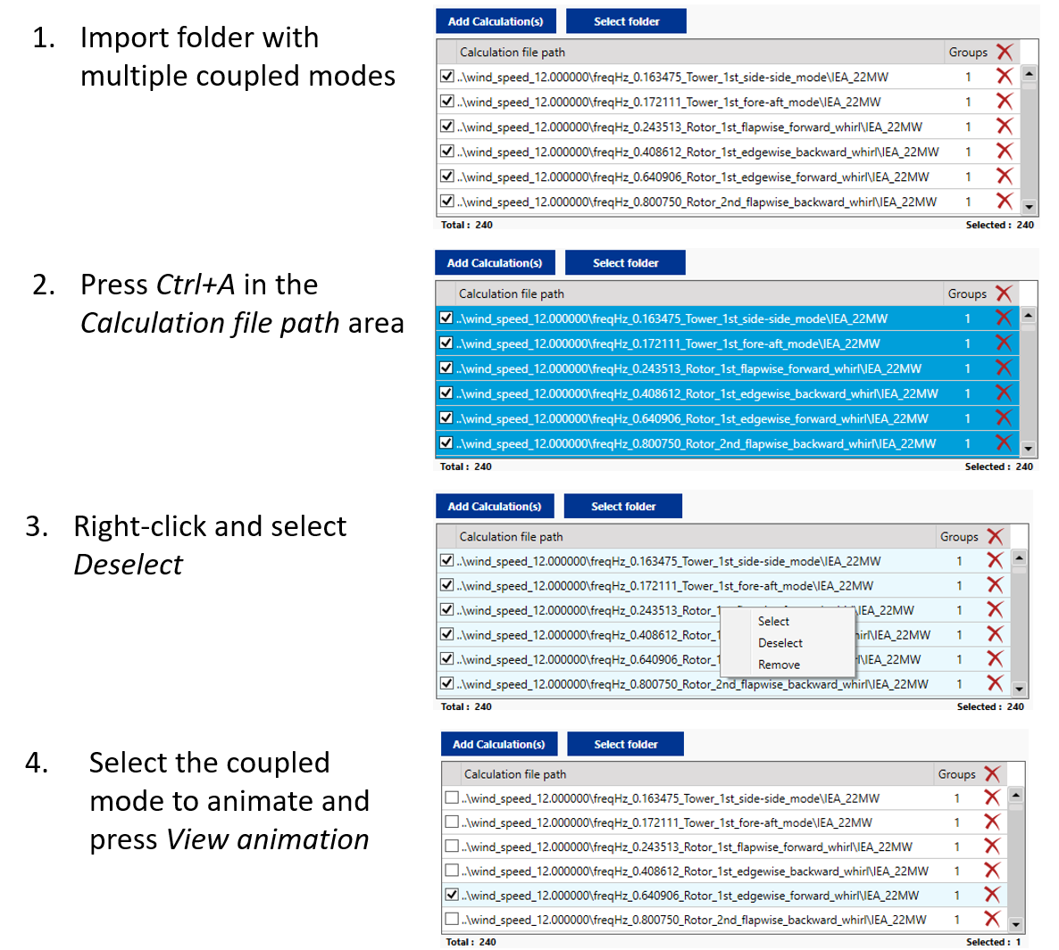
It is possible to either specify a folder with coupled modes in it or a single coupled mode directly. In the example illustrated in Figure 2 it would for example be possible to import all of the coupled modes by selecting folder IEA_22MW_CoupledModeAnimatorResults_ScalingFactor_1.0.
When a folder is selected, all valid coupled modes within that folder become available and are automatically selected. View animation only allows one coupled mode to be selected at a time, so it is necessary to follow the steps described in the figure below:
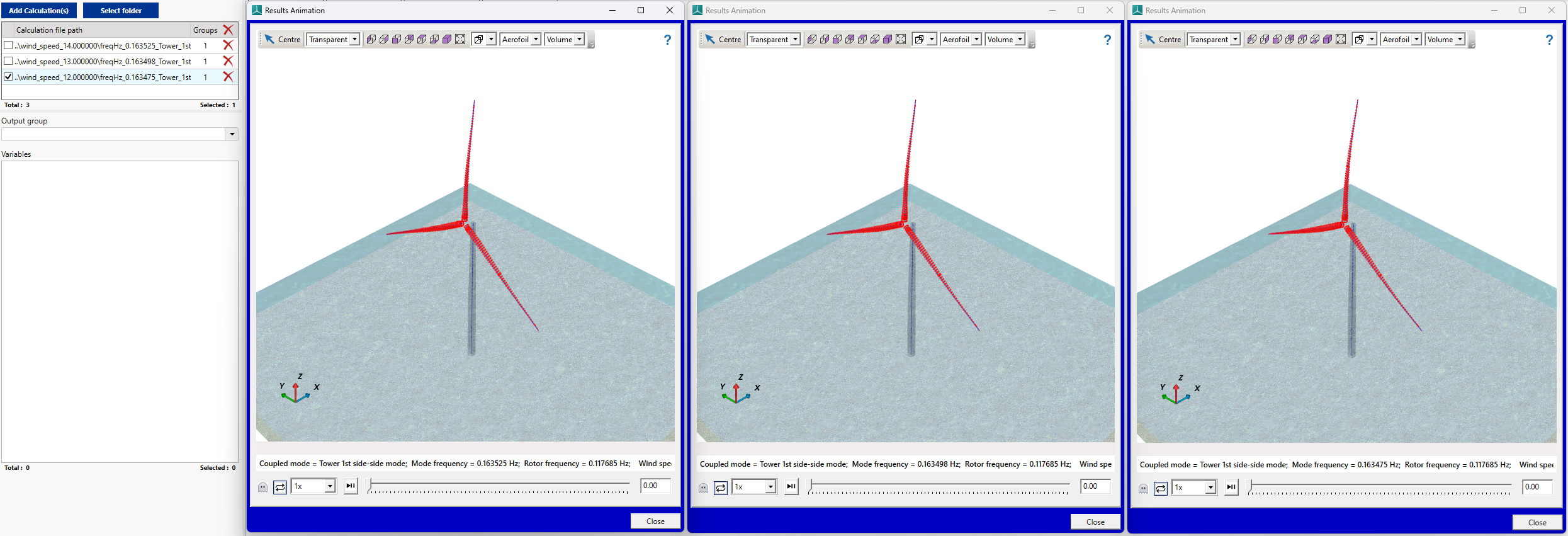
An example below is shown for when a coupled mode is animated:
Multiple instances can be also be open at the same time. For example for inspecting the same coupled mode across different operating points.
Note
For very large models, the default animation view may have a slow frame rate. To improve this, switch from the Transparent view to Solid view in the Results Animation screen.
Running the Coupled Mode Animator from the Command Line with Arguments
The coupled mode animator can be run independently using the executable provided with Bladed, located at: <Bladed installation dir>/CoupledModeAnimator.exe. This allows for customisation of the coupled mode animations by specifying custom arguments during execution. The tool requires a --runpath or -r to the location where Campbell Diagram results are stored. Remember to include the run name in the path.
A complete list of arguments can be seen here or by running the CoupleModeAnimator.exe without any arguments. The more advanced options excludeSteadyStateRotorSpeed, removeRotorResponse and modeOrderThresholdToOutputFullRotation are further detailed below.
Command Line Usage Example
Usage:
CoupledModeAnimator.exe --runpath <value> [Option...]

Required arguments:
-r, --runpath <value>                                 Specifies the path to the linearisation run to compute coupled modes
                                                      (path should include the run name).

Optional arguments:
-h, --help                                            Prints the current help statement to stdout.

-o, --outdir <value>                                  Specifies the root directory to use for results.
                                                      If omitted, results are written to a subdirectory of the input run directory.

-s, --scale <value>                                   Specifies an additional scaling factor to apply to motion animation.
                                                      If omitted, a scaling factor of 1.0 is applied.

-q, --quiet                                           Suppresses progress messages but still displays errors.
                                                      If omitted, program will display progress messages.

-e, --excludeSteadyStateRotorSpeed                    Excludes the steady state rotor speed from the animation.
                                                      If omitted, the steady state rotor speed is included.

-x, --removeRotorResponse                             Sets all rotor rigid body state contributions to coupled modes
                                                      to zero, but the rotor still rotates at a steady state speed.
                                                      Disabled by default.

-m, --modeOrderThresholdToOutputFullRotation <value>  Only coupled modes with a mode order equal to or lower than
                                                      this threshold will have an animation duration that includes
                                                      a full rotor rotation (e.g., Tower 3rd side-side).
                                                      If omitted, a default integer value of 3 is used.
This example runs the coupled mode animator on the specified path, applies a scaling factor of 1.5, suppresses progress messages, removes the steady state rotor speed during the animation, removes rotor rigid body responses, and limits any modes with an order higher than 5 to have the full rotor rotation animated.
Example:
CoupledModeAnimator.exe --runpath "C:\DNV\Bladed\DemoModels\5MW Tripod\lin1" --outdir "C:\Data\CoupledModeAnimator" --scale 1.5 --quiet --excludeSteadyStateRotorSpeed --removeRotorResponse --modeOrderThresholdToOutputFullRotation 5
Exclude Steady State Rotor Speed
This optional argument disables the steady state rotor speed in the animation. While this can be useful for examining specific modes, it is not recommended if you want to fully understand whirling modes or similar phenomena. Use either -e or --excludeSteadyStateRotorSpeed to exclude the steady state rotor speed.
Remove Rotor Response
This optional argument removes the rotor rigid body response from the animation. The rotor rigid body state refers to the rotational degree of freedom of the rotor, where the state value corresponds to the azimuth angle. This option does not remove the steady-state rotor speed from the animation but removes the interaction between the structural modes and the rotor rigid body state.
For example, the interaction between the tower fore-aft motion and the induced wind velocity on the blades, which subsequently changes the torque on the rotor, would be removed from the animation. This can be useful when analysing the behaviour of the structure itself. Use either -r or --removeRotorResponse to enable this option. However, be cautious when using this option, as it may omit important interactions between the rotor and the structure.
Mode Order Threshold to Output Full Rotation
This optional argument specifies the threshold for the coupled mode order to output a full rotor rotation in the animation, as previously explained in Animation Duration. If the mode order is below or equal to this threshold, the animation will display a full rotor rotation, providing a complete view of the mode's behaviour over one cycle. Otherwise, it will only animate a duration equal to the period of the coupled mode.
Adjusting this threshold can help manage the animation duration and data size, ensuring that only the most relevant modes are fully animated. The threshold can be set using the --modeOrderThresholdToOutputFullRotation argument followed by the desired value. If omitted, a default value of 3 is used.
Last updated 16-12-2024