Calculation Method of Turbulent Flow Time Shift
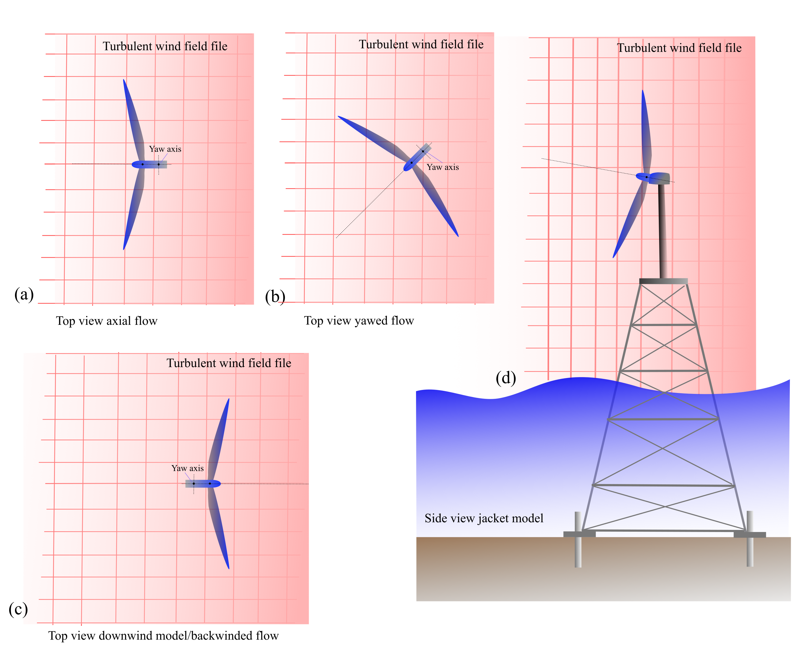
When turbulent flow is applied, Bladed automatically applies a time shift to allow all necessary structures to be covered by the wind data at the start of the simulation (\(t\) = 0 s). This is particularly relevant for wind turbine in yawed orientation, downwind turbine as well as for jacket support structure or floating models. An illustration about the problem to be addressed is given in Figure 1. It can be seen that parameters like the rotor radius, overhang, and tower coordinates are important factors to be considered.
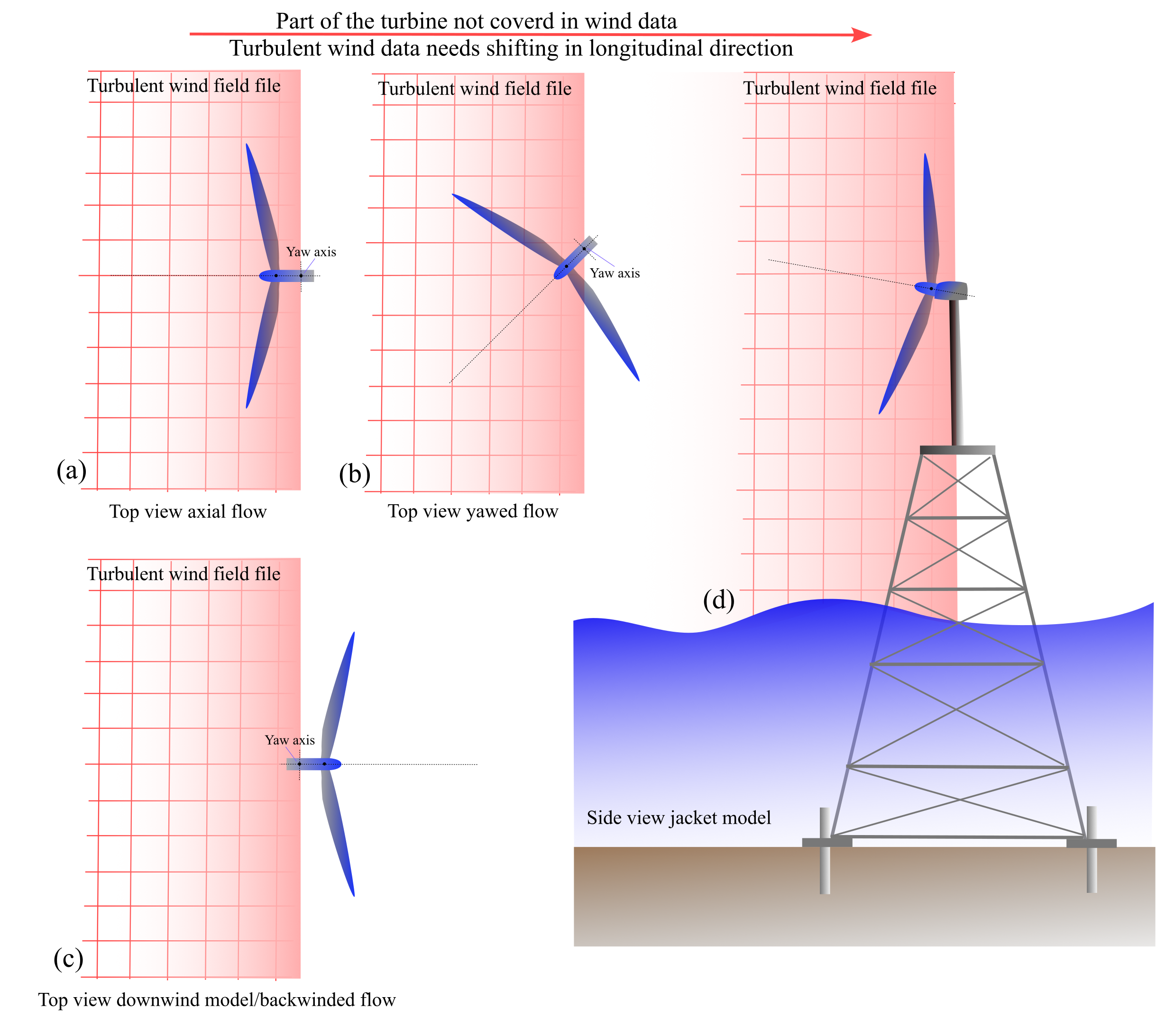
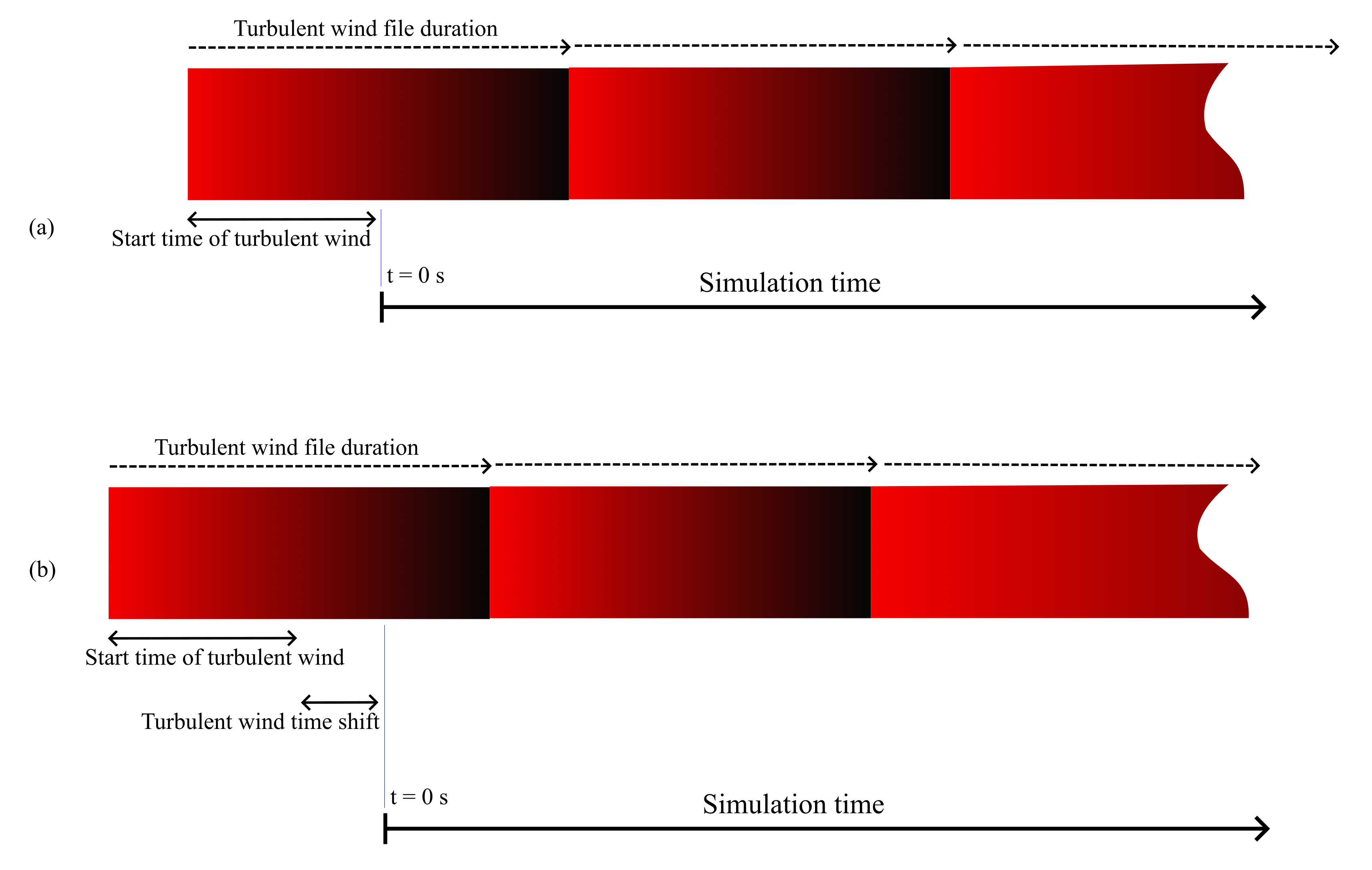
The time shift is applied by simply shifting the wind file to the right side in Figure 1. The magnitude of the time shift is represented by the spatial shift, assuming the wind is propagated at the Mean wind speed value, please see the usage of the turbulent flow data in the time domain calculations. The length of the time shift is calculated by
with,
Variables \(R\), \(L_{Overhang}\), \(H_{offset}\) define the rotor radius, rotor overhang and the horizontal offset of the rotor centre, respectively. To ensure the wind covers entire turbine structures, \(L_{tower}^{extrema}\) is added which measures the extrema of the tower coordinate measured from the tower centre. For floating turbines, sea depth (\(z_{sea}\)) is used as an estimate for maximum movement of the turbine. Therefore, it is included in the formulation where \(\phi\) equals to unity for floating wind turbine calculations while it is zero otherwise. This way, it is possible to safely include turbulent wind data even for the first time instance at (\(t\) = 0 s). An overview of the wind field location after time shifting is given in Figure 2 and Figure 3.
Last updated 28-08-2024