Eddy Viscosity model
The Eddy Viscosity wake model is a CFD calculation representing the development of the velocity deficit field using a finite-difference solution of the thin shear layer equation of the Navier-Stokes equations in axi-symmetric co-ordinates. The Eddy Viscosity model automatically observes the conservation of mass and momentum in the wake. An eddy viscosity, averaged across each downstream wake section, is used to relate the shear stress to gradients of velocity deficit. The mean field can be obtained by a linear superposition of the wake deficit field and the incident wind flow.
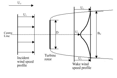
Below is an explanation of how this theory has been adapted for use within WindFarmer. An illustration of the wake profile used in the Eddy Viscosity model is shown in the figure below.

Wake profile used in the Eddy Viscosity model
Model equations
The Navier-Stokes equations with Reynolds stresses and the viscous terms dropped gives [6]:
$$U\frac{\partial U}{\partial x} + V\frac{\partial U}{\partial r} = \frac{- 1}{r}\frac{\partial(r\overline{\textrm{uv}})}{\partial r}$$
The turbulent viscosity concept is used to describe the shear stresses with an eddy viscosity defined by [7]:
$$\varepsilon(x) = L_{m}(x).U_{m}(x)$$
and $$- \overline{\textrm{uv}} = \varepsilon\frac{\partial U}{\partial r}$$
Lm and Um are suitable length and velocity scales of the turbulence as a function of the downstream distance x but independent of r. The length scale is taken as proportional to the wake width Bw and the velocity scale is proportional to the difference Ui – Uc across the shear layer.
This permits the shear stress terms $\overline{\textrm{uv}}$ to be expressed in terms of the eddy viscosity. The governing differential equation to be solved becomes:
Equation 1
$$U\frac{\partial U}{\partial x} + V\frac{\partial U}{\partial r} = \frac{\varepsilon}{r}\frac{\partial(r\partial U/\partial r)}{\partial r}$$
The ambient wind flow for a wind farm must be considered as turbulent. Therefore, the eddy viscosity in the wake cannot be wholly described by the shear contribution alone but an ambient term is included. [8]
$$\varepsilon = FK_1B_w(U_i-U_c)+ \varepsilon_{amb}$$
where the filter function $F$ is a factor applied for near wake conditions. This filter can be introduced to allow for the build up of turbulence on wake mixing. The dimensionless constant $K1 is a constant value over the whole flow field.
The ambient eddy viscosity term is calculated by the following equation proposed by Ainslie [8]:
$$\varepsilon_{\textrm{amb}} = F \cdot {K_{k}}^{2} \cdot I_{\textrm{amb}}/100$$
Kk is the von Karman constant with a value of 0.4. As a result of comparisons between the model and measurements reported by Taylor in [9] the filter function F is fixed at unity.
Initialisation of the model
The centre line velocity deficit Dmi can be calculated at the start of the wake model (two diameters downstream) using the following empirical equation proposed by Ainslie [8]:
$$D_{textrm{mi}} = 1 - \frac{U_{c}}{U_{i}} = C_{t} - 0.05 - \lbrack \left( 16C_{t} - 0.5 \right) I_{\textrm{amb}}/1000\rbrack$$
Assuming a Gaussian wind speed profile and momentum conservation, an expression for the wake width is obtained.
$$B_{w} = \sqrt{\frac{3.56C_{t}}{8D_{m}(1 - 0.5D_{m})}}$$
The wake width Bw used is defined as 1.89 times the half-width of the Gaussian profile.
Using the above equations, the average eddy viscosity at a distance 2D downstream of the turbine can be calculated.
Wake development
The wake development is calculated by applying a parabolic solution to the RANS equations (Equation 1) starting from the most upstream turbine.
For each downstream turbine that falls inside the wake, the incident wind speed needs to be calculated. The velocity profile across the turbine affected by wake is calculated by assuming a Gaussian profile based on the centre line velocity at that distance downstream. If some of the rotor is outside the wake, then the wind speed for that portion of the rotor is set as the incident wind speed of the turbine creating the wake. The velocity profile across the turbine rotor at hub height is integrated to produce a mean wind speed incident across the rotor at the height. This is assumed to represent the incident wind speed across the whole rotor disc.
When multiple turbine types are present, any differences in hub height and rotor diameter are taken into consideration.
Turbulence intensity
The Eddy Viscosity model relies on a value of incident ambient turbulence intensity. For a turbine in the free wind stream, the calculation must be initiated using the ambient turbulence level. For a turbine within a wind farm, it is necessary to calculate the increased turbulence level that results from the presence of upstream turbines.
Wind farm turbulence levels are calculated using an empirical characterisation developed by Quarton and Ainslie [10]. This characterisation enables the added turbulence in the wake (Iadd) to be defined as a function of ambient turbulence (Iamb), the turbine thrust coefficient (Ct), the distance downstream from the rotor plane (x) and the length of the near wake:
$$I_{\textrm{add}} = 4.8{C_{t}}^{0.7}{I_{\textrm{amb}}}^{0.68}\left( x/x_{n} \right)^{- 0.57}$$
where xn is the calculated length of the near wake using the method proposed in [11] [12].
The characterisation was subsequently amended slightly to improve the prediction, as shown below [13]:
$$I_{\textrm{add}} = 5.7{C_{t}}^{0.7}{I_{\textrm{amb}}}^{0.68}\left( x/x_{n} \right)^{- 0.96}$$
Using the value of added turbulence and the incident ambient turbulence, the turbulence intensity at any turbine position in the wake can be calculated. The model also accounts for the turbine not being completely in the wake.
The ambient turbulence intensity is best derived from measurements.
Terrain modification of the wake and turbulence
The wind flow around a wind turbine, including the wake, will be accelerated when passing over terrain. This acceleration is calculated by the wind flow model and affects both mean wind speeds and turbulence. WindFarmer allows optional consideration of this effect on the mean wind speed (incident on the next turbine) by scaling the wake deficit with the terrain speed-up derived from the flow model.
Using the assumption that the standard deviation stays constant while the mean wind speed is modified over the terrain, WindFarmer also varies the turbulence intensity over a given terrain. Three-dimensional modifications of the turbulence and terrain-induced modifications of the turbulence spectrum are neglected.