Shadow Flicker
The Shadow Flicker tools in WindFarmer allow you to create maps of shadow flicker occurrence and to analyse the shadow flicker at specific points, known as receptors. This information can be used to design and operate the wind farm in a way that minimises the annoyance to people.
Inputs to Shadow Flicker
The following inputs to the WindFarmer model are required to produce an estimate of the shadow flicker effect at the wind farm:
| Input | note |
|---|---|
| Site location | Latitude, Longitude of where the wind farm(s) is located, set in Site Setup |
| Receptors | Define the locations and receptor settings in Map > Receptor Location if you wish to evaluate detailed flicker results at precise locations. Receptors are not used for flicker maps. |
| Turbine locations | Define turbine locations in Design > Place turbines |
| Turbine dimensions | hub height, rotor diameter, distance between rotor and turbine tower centre are all required. Set these in Components > Turbine types |
| Gridded elevations | Gridded elevations must be imported, downloaded or converted from vector contours in Map > Elevations |
| Shadow flicker settings | In Environment > Shadow Flicker define parameters that define the accuracy of the calculation and/or specify restrictions for receptors. |
Receptors
Define the receptor locations by pasting them in to the table or placing them on the map.
The receptor has settings that define a hemispherical field of view. The default settings make "green house" assumptions where flicker from any direction is considered. The bearing and tilt direct the field of view in a chosen direction to ignore incident flicker behind the receptor field of view to allow modelling of windows in to buildings that point in a particular direction.
| Setting | Definition |
|---|---|
| Tilt | A positive tilt is the angle of the view hemisphere window from the vertical. A tilt of 90 describes a normal vertical window. The default tilt of 0 means the receptor is a green house. |
| Bearing | Defines the direction of the flicker viewing hemisphere. If the tilt = zero this setting has no impact. |
| Height | The height above ground of the receptor, [default = 2m] |
Shadow flicker settings
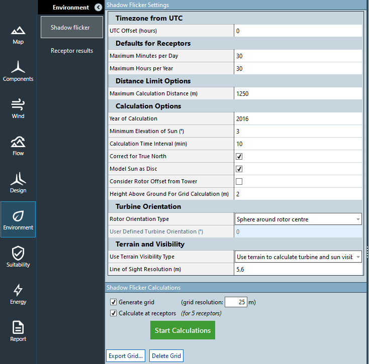
In Environment > Shadow Flicker you can define parameters that define the accuracy of the calculation and run the shadow flicker calculation.
| Setting | Definition |
|---|---|
| UTC offset | Set your time zone as an offset from UTC. This is important for flicker reporting for receptors. |
| Maximum minutes per day | Receptors with total flicker on any one day above this limit contravene regulations. |
| Maximum minutes per year | Receptors with total flicker minutes over the year above this limit contravene regulations. |
| Maximum calculation distance | Beyond this distance from a turbine the flicker is assumed to be zero. |
| Year of calculation | We consider the shift of the sun position by a quarter day each year and the different number of days when it is a leap year. The shadow flicker calculation simulates effects over 1 full year |
| Minimum elevation of the Sun | Flicker is not calculated at elevations below this value. [Default = 3 degrees above the horizon] |
| Calculation time interval | The highest resolution possible is 1 minute, which is recommended to produce detailed results for receptors. Lower resolution can be used for faster simulations. |
| Correct for true north | WindFarmer can consider the difference between True North and Grid North. It is recommended that this correction is applied. The correction is based on the global co-ordinate system used in the workbook. If not checked, it is assumed that True North and Grid North are the same. Note that turbine rotor orientation and receptor bearings need to be defined with respect to Grid North. [Default = true] |
| Model sun as a disk | The default in shadow flicker calculations is that the sun is assumed to be a point [Default = false]. Setting this option to true models the sun as a disc. This worst case option leads to higher shadow flicker times, especially close to the turbines. See the calculation reference for more detail. |
| Consider rotor offset from tower | The calculation of shadow flicker automatically recognises the offset distance between the tower coordinates and the centre of the turbine rotor. This can be disabled if required. |
| Height above ground for grid calculation | The height at which we calculate flicker grids. [Default = 2m ] |
Turbine orientation options
| Setting | Definition |
|---|---|
| Spherical model | Uses a sphere of radius equal to rotor radius to represent the area causing the potential shadow flicker. |
| Rotor following the azimuth angle of the sun | Worst case: the rotor axis is 180 degrees from the sun's azimuth. |
| Fixed rotor orientation for all turbines | The rotor faces the defined wind direction. Use this when you wish to frequency weight results or have a unidirectional wind rose. |
Terrain and visibility options
WindFarmer optionally allows you to detect if the direct line of sight between receptor and turbine, or between the turbine and the sun is blocked by terrain features.
| Terrain and visibility type option | Definition |
|---|---|
| No calculation of visibility due to terrain | Represents a worst case and results in a fast calculation times. Could be used on flat sites for fast computation. |
| Use terrain to calculate turbine visibility | Line of sight between turbines and receptor or each point on the map is checked for intersection. |
| Use terrain to calculate turbine and sun visibility | Most accurate and longer computation. Line of sight between both turbines and sun the receptors/map points are checked for intersection. |
Line of site resolution defines how regularly the line of site is checked for intersection. Smaller distances result in more computation. Consider the resolution of the gridded elevations when setting this.
Shadow flicker Mapping
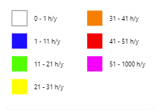
To calculate a shadow flicker map check the "Generate grid" box and specify a grid resolution.
The shadow flicker map data may be exported in contour or grid formats.

Considering the impact of wind direction
Using the automation module a dictionary of fixed rotor orientations with corresponding directional frequencies can be used to consider the impact of wind direction on the shadow flicker results. Flicker grids and receptor results are then simulated for each fixed rotor direction and the frequency weighted sum is calculated to define the overall flicker.
Consideration of cloud cover
Using the automation module a time series of weightings can be applied to the shadow flicker results to scale them to account for cloud cover. A weighting of 0.0 means for fully covered skies and will result in zero flicker. 1.0 corresponds to clear sky and the unweighted shadow flicker result would be used. If you apply a weighting of 0.5 this halves the flicker prediction from the clear sky case.
The calculation accepts daily weightings but a helper method is provided to convert monthly weightings to daily weightings.

